
Photoelectricity integrated light source

A light source, photoelectric technology, applied in the direction of electric light source, light source, electrical components, etc., can solve the problems of large interference of energy storage inductance and filter inductance, chaotic layout, etc., to achieve automatic production, improve production efficiency, and reduce defect rate. Effect

Pending Publication Date: 2019-03-29
中山市同曦照明科技有限公司
View PDF10 Cites 0 Cited by
  • Summary
  • Abstract
  • Description
  • Claims
  • Application Information

AI Technical Summary

Problems solved by technology

[0006] ②The layout is relatively chaotic, which makes the interference between the energy storage inductor and the filter inductor larger;

Method used


Image

  • Photoelectricity integrated light source
  • Photoelectricity integrated light source
  • Photoelectricity integrated light source

Examples

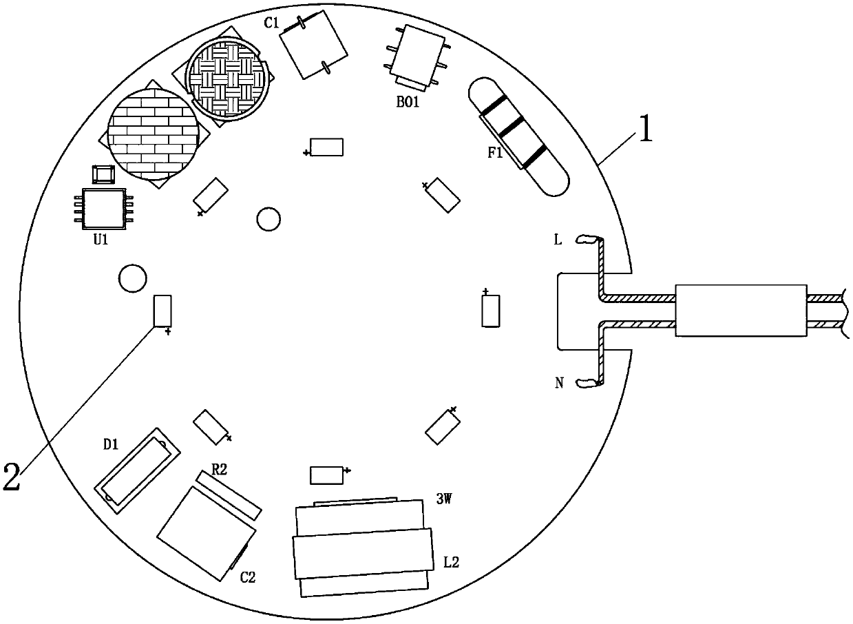
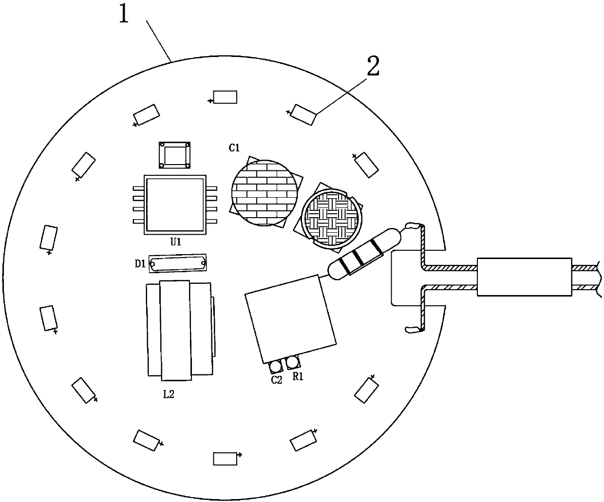

Embodiment Construction

[0025] The following will clearly and completely describe the technical solutions in the embodiments of the present invention with reference to the accompanying drawings in the embodiments of the present invention. Obviously, the described embodiments are only some, not all, embodiments of the present invention. Based on the embodiments of the present invention, all other embodiments obtained by persons of ordinary skill in the art without making creative efforts belong to the protection scope of the present invention.

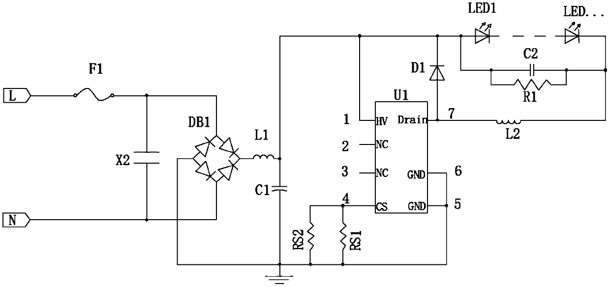
[0026] see Figures 1 to 3 , the present invention provides a technical solution:

[0027] An optoelectronic integrated light source, comprising a circuit substrate 1, on which a power line, a Led light source 2 and an IC circuit module are arranged, and the power line, the Led light source 2 and the IC circuit module are rationally integrated on the circuit substrate 1 on.

[0028] IC circuit module includes integrated circuit U1, energy storage inductor L1...


PUM


Abstract

The invention discloses a photoelectricity integrated light source. The photoelectricity integrated light source includes a circuit substrate, wherein a power line, an LED light source and an IC circuit module are arranged on the circuit substrate; and the power line, the LED light source and the IC circuit module are integrated on the circuit substrate reasonably. By integrating and setting the light source on the circuit board in order, the photoelectricity integrated light source has the advantages of 1) improving the production efficiency, and being able to realize automatic production; 2)being less in the process of detection than the prior art; 3) being precisely controllable in quality, and reducing the fraction defective; and 4) solving photoelectric mutual interference, and beingeasy to pass 3C authentication.

Description

technical field [0001] The invention relates to the technical field of optoelectronic integration, in particular to an optoelectronic integrated light source. Background technique [0002] Traditional optoelectronic integrated light sources usually consist of two methods: [0003] 1. The light source board composed of LED is connected with a separate driving power supply. Therefore, the processing is slow and requires high precision, so there are many follow-up inspection procedures, the error rate and processing efficiency are greatly reduced, the yield rate is low, and the waste is serious. [0004] 2. The drive power and light source are integrated. There are the following problems in this composition method in technology: [0005] ①The distance between the energy storage inductor and the filter inductor in the IC circuit module is not easy to control. The distance between the two should be considered during actual processing to avoid the influence between the two, so ...

Claims


Application Information

Patent Timeline
Patent Type & Authority Applications(China)
IPC IPC(8): H05B37/02
CPCH05B47/10
Inventor 唐益
Owner 中山市同曦照明科技有限公司
Learn More