Wiping mechanism of sweeping machine and sweeping machine

A technology of wiping mechanism and sweeping machine, which is applied in the direction of manual sweeping machinery and machine parts, etc. It can solve the problems that the head of the sweeping machine collides with slopes or obstacles, is not suitable for ordinary household use, and the tracks are prone to idling, etc., and achieves the purpose of wiping Good effect, compact structure, low noise effect

Pending Publication Date: 2019-04-02
ZHEJIANG DIMEI INTELLIGENT TECH CO LTD
View PDF0 Cites 0 Cited by
  • Summary
  • Abstract
  • Description
  • Claims
  • Application Information

AI Technical Summary

Problems solved by technology

[0004] The general sweeping machine is like the structure proposed by the above-mentioned invention. It generally includes a main body, a brush for cleaning the ground, and a control system installed inside the main body to control the work of the entire mechanism. The effect it can achieve is only cleaning the ground. Cleaning, the effect is relatively simple; there are also some sweepers equipped with mopping structures, but they are often large in size and take up a lot of space when stored, so they are not suitable for ordinary households.
[0005] At present, some sweepers are equipped with crawler-type forward wheels below. This combination of pulleys is convenient for climbing, which makes the sweeper more applicable. The sweeper also includes a machine head. The fuselage is fixedly connected. When going uphill or touching an obstacle, it is easy to cause the nose to collide with the slope or obstacle. Long-term use will easily cause unnecessary damage, and when the nose drives up the slope , will cause the track to hang in the air, and the track is prone to idling, which will affect the track

Method used


Image

  • Wiping mechanism of sweeping machine and sweeping machine
  • Wiping mechanism of sweeping machine and sweeping machine
  • Wiping mechanism of sweeping machine and sweeping machine

Examples


Embodiment Construction

[0041] Below in conjunction with accompanying drawing, the present invention will be further described with specific embodiment, see Figure 1-Figure 13 ,

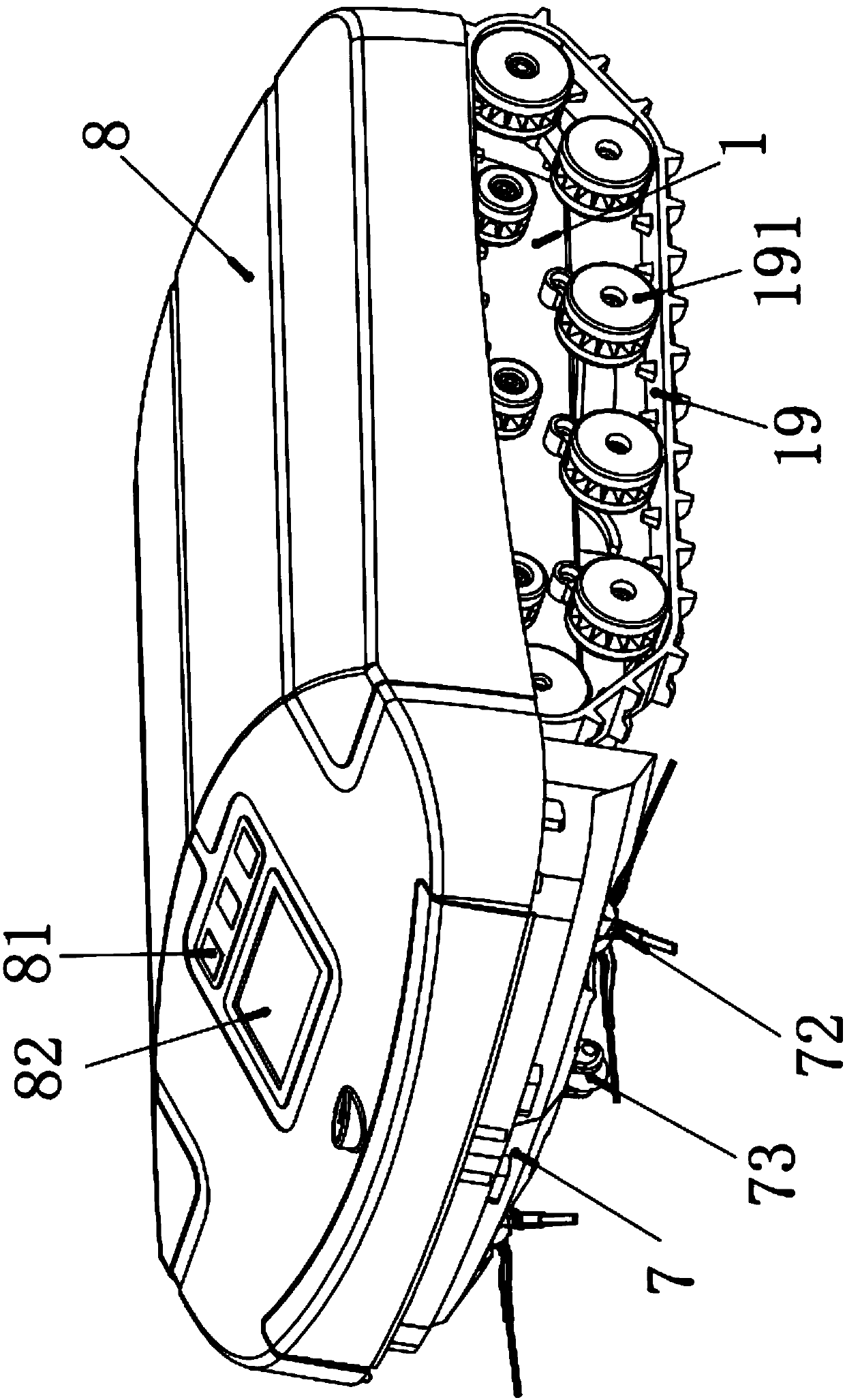
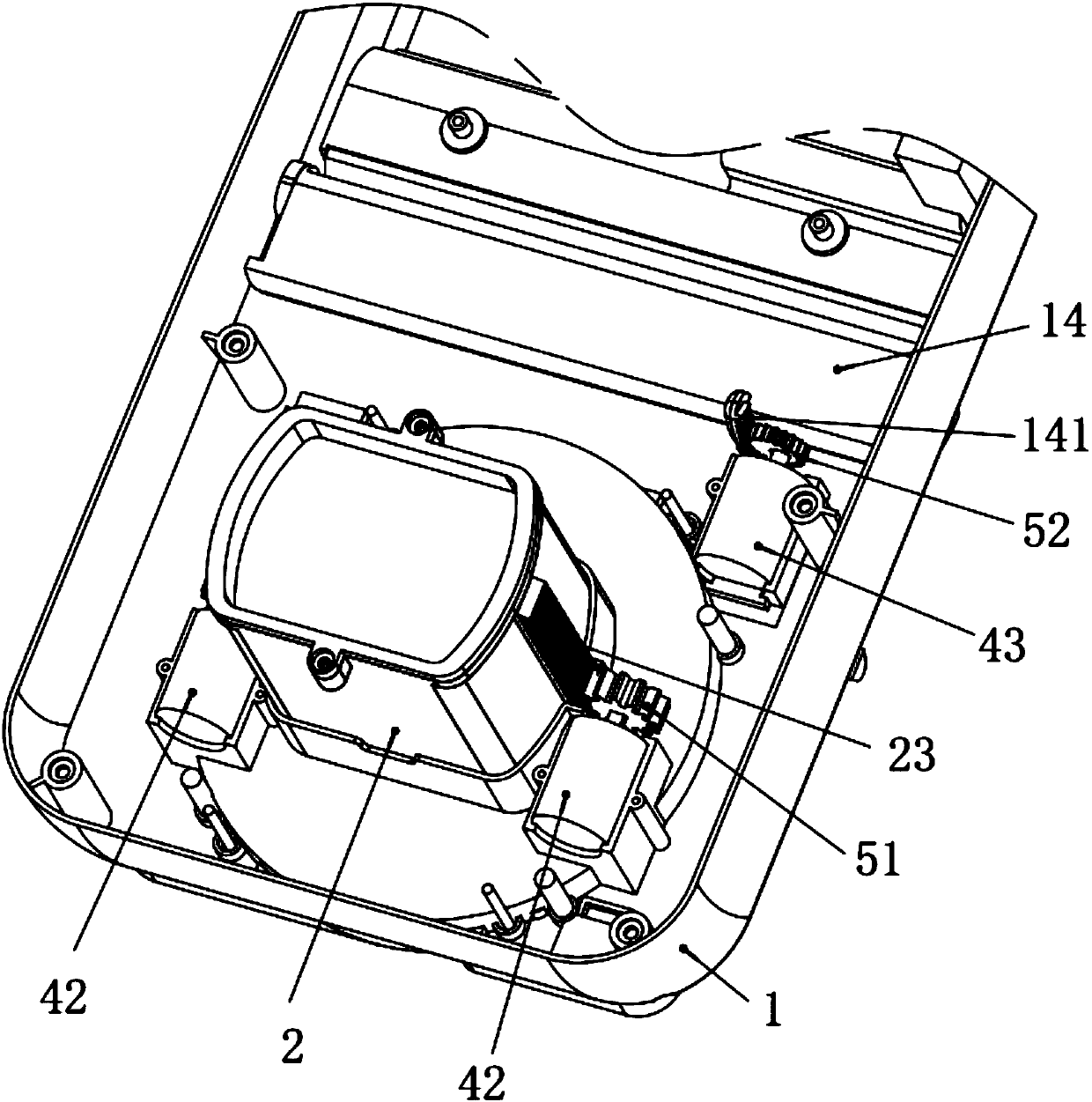
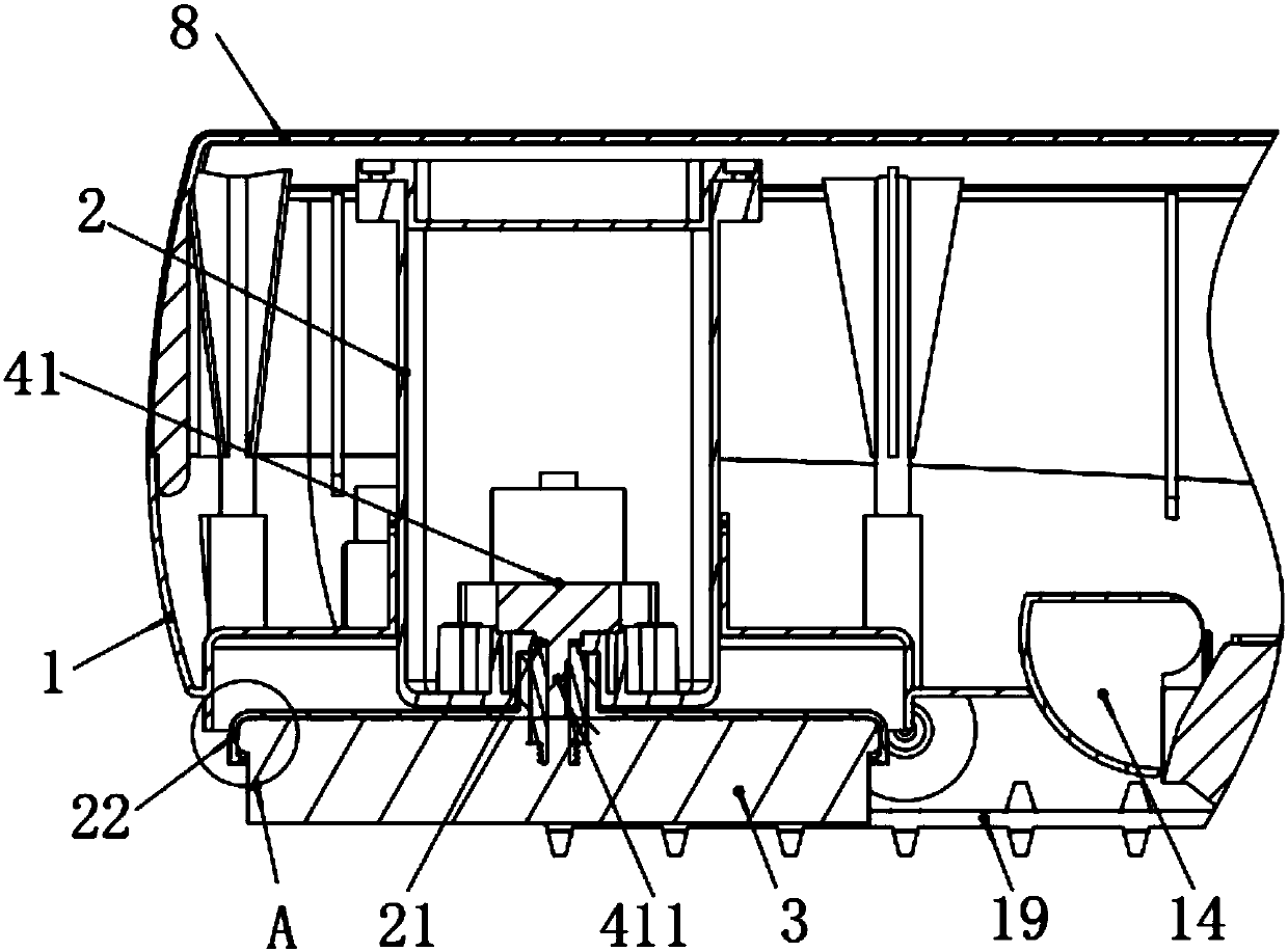
[0042] A floor wiping mechanism of a sweeper, comprising a casing 2 installed on a main body 1 of the sweeper, and,

[0043] Drive device 1, the drive device 1 is installed inside the casing 2, the drive device 1 extends out of the lower end of the casing 2 and is connected with a wiper 3 for wiping the ground, and the wiper 3 rotates under the drive of the drive device 1;

[0044] The second driving device, the second driving device is installed inside the main body 1 of the sweeper, and drives the casing 2 to move up and down. The mopping mechanism proposed by the present invention has the functions of mopping and cleaning through lifting up and down and rotating.

[0045] Described driving device one comprises driving motor one 41, and the main body of driving motor one 41 is positioned at described casing 2 inside, a...


PUM


Abstract

The invention belongs to the technical field of electric sweeping machines, and particularly relates to a wiping mechanism of a sweeping machine and the sweeping machine. The wiping mechanism comprises a casing mounted on a sweeping machine main body, a driving device 1 and a driving device 2. The driving device 1 is installed inside the casing, and the driving device 1 extends from the lower endof the casing and is rotationally connected with a wiper for wiping the ground. The driving device 2 is installed in the sweeping machine main body to drive the casing to move up and down. The sweeping machine comprises the wiping mechanism, the sweeping machine main body and a control system for driving the whole sweeping machine body to work, the wiping mechanism is installed at the rear of thesweeping machine main body, a machine head is mounted at the front end of the sweeping machine main body, and mobile devices for causing the sweeping machine to advance on the ground are installed onboth sides of the sweeping machine. The wiping mechanism provided by the invention enables the sweeping machine to have an added wiping function on the basis of an original cleaning function, and thewiping mechanism can perform automatic cleaning, is convenient to use, has good cleaning effect, and saves time and labor.

Description

technical field [0001] The invention belongs to the technical field of electric sweepers, in particular to a sweeping mechanism of the sweeper and the sweeper. Background technique [0002] With the continuous improvement of people's living standards, sweepers have gradually entered the homes of ordinary people, becoming an indispensable cleaning helper for every family, and with the development of intelligence, they have gradually replaced manual cleaning. A general sweeper is equipped with a brush structure under the fuselage, and the sweeper moves on the ground to clean the garbage and dust on the ground through the brush and the dust collection components inside the fuselage. [0003] China Utility Model Patent Application No.: 2015206741854 proposes a sweeper, including a fuselage, a cleaning portion and a rotating portion. The cleaning portion is rotatably arranged at the bottom of the fuselage through the rotating portion. A rotatable cleaning part is set at the bott...

Claims


Application Information

Patent Timeline
Patent Type & Authority Applications(China)
IPC IPC(8): A47L11/24A47L11/40
CPCA47L11/24A47L11/40
Inventor 曹恒
Owner ZHEJIANG DIMEI INTELLIGENT TECH CO LTD
Why Eureka
Try Eureka