
Automatic thread punching die for lock support

An automatic punching and locking support technology, which is applied in the field of auto parts production, can solve the problems such as the difficulty of demoulding the mold cavity, and achieve the effects of increasing profits, saving production costs, and improving work efficiency

Pending Publication Date: 2019-04-02
无锡市振华亿美嘉科技有限公司
View PDF0 Cites 0 Cited by
  • Summary
  • Abstract
  • Description
  • Claims
  • Application Information

AI Technical Summary

Problems solved by technology

[0003] In view of the above existing problems, the present invention provides a lock support automatic thread punching die to solve the problem in the prior art that it is difficult to demould the mold die after the lock support punches the thread. The die is set as a detachable fixed structure up and down, Separating the upper and lower structures of the die can easily realize the demoulding operation of the die die. The operation process is simple and fast, which improves the work efficiency of the lock support punching thread; avoids damage to the die during the demoulding process and prolongs the life of the core. Long service life, save the cost of the enterprise

Method used


Image

  • Automatic thread punching die for lock support
  • Automatic thread punching die for lock support
  • Automatic thread punching die for lock support

Examples


Embodiment 1

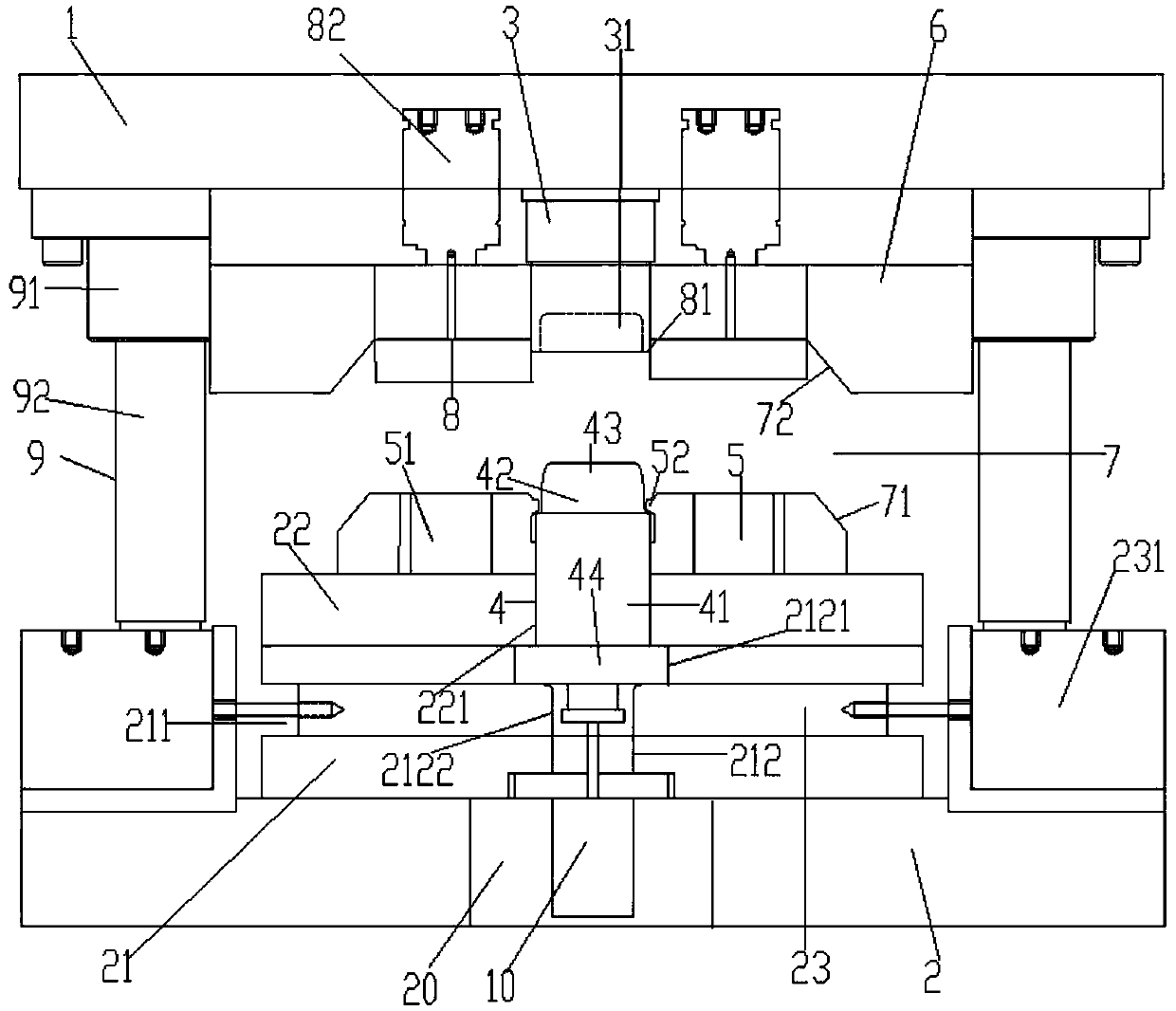
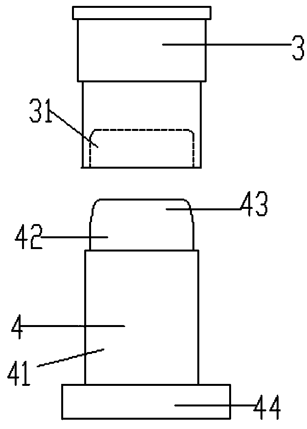
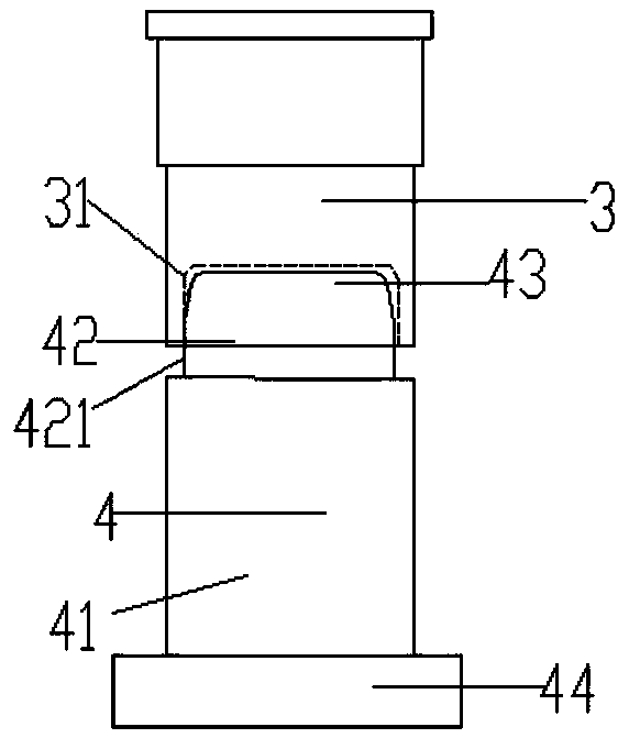
[0025] like figure 1 As shown, the lock support automatic punching thread die provided by Embodiment 1 of the present invention includes a mold base and a mold core arranged on the mold base; the mold base includes an upper mold base 1 and a lower mold base 2 arranged below the upper mold base 1 The mold core includes a die; the die includes an upper mandrel 3 and a lower mandrel 4; the lower mandrel 4 is vertically arranged on the upper end surface of the lower mold base 2; the lower mandrel 4 includes a body 41 and a convex body arranged on the upper part of the body The raised portion 42; the body 41 and the raised portion 42 are cylindrical; the cross-sectional radius of the raised portion 42 is less than the cross-sectional radius of the body 41; the upper mandrel 3 is vertically arranged on the lower end surface of the upper mold base 1; as figure 2 As shown, the lower part of the upper mandrel 3 is cylindrical; the cross-sectional radius of the lower part of the upper ...


PUM


Abstract

The invention discloses an automatic thread punching die for lock support and relates to the field of car part production. The automatic thread punching die comprises a die base and a die core. The die core comprises a female die body. The female die body comprises an upper core bar and a lower core bar. The upper core bar and the lower core bar are detachably fixed. The lower core bar comprises abody and a protruding portion arranged on the upper portion of the body. The body and the protruding portion are of a cylinder shape. The radius of the cross section of the protruding portion is smaller than the radius of the cross section of the body. The lower portion of the upper core bar is of a cylinder shape. The radius of the cross section of the lower portion of the upper core bar is equal to that of the cross section of the body. The axis of the lower portion of the upper core bar, the axis of the protruding portion and the axis of the body coincide. The lower end face of the upper core bar is provided with a concave opening portion fit with the protruding portion in a corresponding manner. The vertical height of the concave opening portion is smaller than that of the protrudingportion. According to the automatic thread punching die for lock support, the demoulding process is easy to operate, the working efficiency can be improved, damage to the female die body in the demoulding process is avoided, the service life of the die core is prolonged, and the cost of enterprises is saved.

Description

technical field [0001] The invention relates to the field of auto parts production, in particular to a lock support automatic thread punching die. Background technique [0002] Lock braces are an important auto accessory. The lock support is provided with an external thread, and the traditional lock support thread forming process generally adopts an extrusion process. The lock support mouth after extrusion thread forming has an inwardly protruding convex ring structure, which is easy to cause the problem of difficult demoulding of the die die. In the prior art, it is necessary to take out the die and the product at the same time after stamping, and perform separate demoulding work at the auxiliary station when the die is demolded by the lock support punching thread die. Due to the need for separate demoulding work, the work efficiency of the lock support punching thread is reduced, and the die is easily damaged during the process of taking the die, which shortens the servi...

Claims


Application Information

Patent Timeline
IPC IPC(8): B21D37/10
CPCB21D37/10
Inventor 苏靖波
Owner 无锡市振华亿美嘉科技有限公司
Learn More