Rotary pipeline clamping device

A clamping device and rotary technology, applied in the direction of roller table, transportation and packaging, conveyor, etc., can solve the problems of many processes, slow production cycle, cumbersome operation steps, etc., to reduce friction, reduce the probability of failure, Structurally Reliable Effects

Active Publication Date: 2019-04-02
EZHOU XINGXIN BUILDING MATERIALS
View PDF9 Cites 5 Cited by
  • Summary
  • Abstract
  • Description
  • Claims
  • Application Information

AI Technical Summary

Problems solved by technology

Existing cutting equipment can only cut multi-reinforced steel-plastic composite pipes in a static state, which has the defects of many processes, cumbersome operation steps, and slow production cycle

Method used


Image

  • Rotary pipeline clamping device
  • Rotary pipeline clamping device

Examples


Embodiment 1

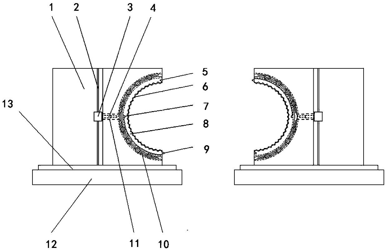
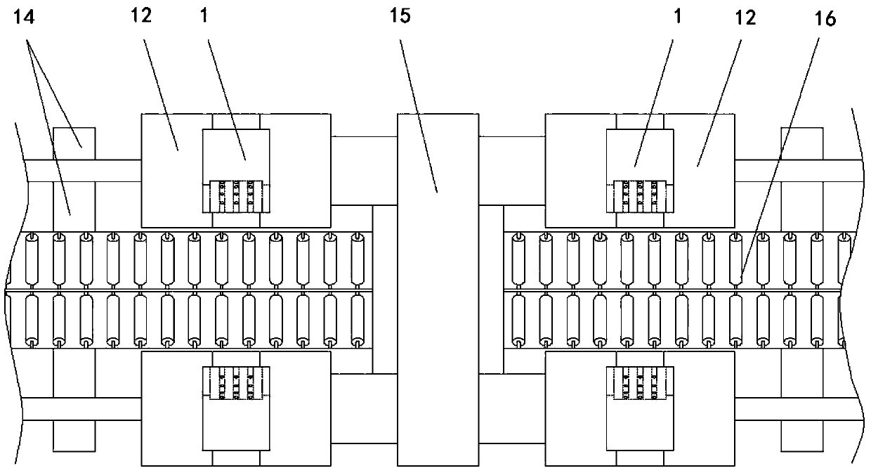
[0022] Such as figure 1 with figure 2 As shown: a rotary pipe clamping device, including a control system placed on a bracket 14 and two clamping blocks 1, the two clamping blocks 1 are symmetrically arranged on both sides of the pipeline conveying device 16, and the two clamping blocks 1 are respectively A transverse driving device is arranged on the slide plates 12 on both sides of the pipeline conveying device 16, and the two slide plates 12 are connected as a whole through a connecting piece. The opposite sides of the two clamping blocks 1 are symmetrically provided with arc-shaped chute, and an arc-shaped clamping piece 8 is respectively slidably arranged in the arc-shaped chute of the two clamping blocks 1, and the groove of the arc-shaped clamping piece 8 and the arc-shaped chute A plurality of arc-shaped brackets 10 with steel balls are arranged between the walls, and the arc-shaped brackets 10 are fixedly arranged on the inner wall of the arc-shaped chute. The stru...


PUM


Abstract

The invention provides a rotary pipeline clamping device. The rotary pipeline clamping device comprises a control system and two clamping blocks, wherein the control system and the two clamping blocksare arranged on a bracket; arc-shaped sliding grooves are symmetrically formed in the opposite sides of the two clamping blocks, arc-shaped clamping pieces are slidably arranged in the arc-shaped sliding grooves of the two clamping blocks, and when the two arc-shaped clamping pieces are spliced into a circle, a splicing convex block at the end of one of the arc-shaped clamping pieces is insertedinto a splicing concave pit in the corresponding end of the other arc-shaped clamping piece; positioning pits are further formed in the back faces of the two arc-shaped clamping pieces, and clamping piece positioning mechanisms are arranged in the clamping blocks; and the control system is used for controlling working states of a transverse driving device, an axial driving device and a telescopicair cylinder. The clamping device can axially move along with the pipeline and can further allow the pipeline to rotate freely, a multiple-reinforced steel-plastic composite pipe in the moving state can be clamped and positioned, the rotary pipeline clamping device is novel in design and reliable in structure and has outstanding practicability and remarkable progress.

Description

technical field [0001] The invention relates to a device for clamping a pipeline. After clamping the pipeline, the clamping device does not affect the motion state of the pipeline itself, and the pipeline can still rotate and move forward in the axial direction, which belongs to the composite pipe clamp Supporting equipment technical field. Background technique [0002] In the process of producing multi-reinforced steel-plastic composite pipes, when cutting multi-reinforced steel-plastic composite pipes, it is often necessary to stop the equipment to cut them, because the pipe not only moves forward in the axial direction but also keeps rotating with. Existing cutting equipment can only realize the cutting of multi-reinforced steel-plastic composite pipes in a static state, which has the defects of many processes, cumbersome operation steps and slow production tempo. Contents of the invention [0003] Aiming at the above-mentioned defects of the existing multi-reinforced...

Claims


Application Information

Patent Timeline
Patent Type & Authority Applications(China)
IPC IPC(8): B65G47/22B65G13/00B26D7/02
CPCB26D7/02B26D2007/013B65G13/00B65G47/22B65G2201/0276
Inventor 李广忠姜金华全姗姗熊学识戈国庆杜希冰
Owner EZHOU XINGXIN BUILDING MATERIALS
Why Eureka
Try Eureka