Ultrasonic flaw detection method and device for upper arcs and lower jaw areas on both sides of rail head

A technology of ultrasonic flaw detection and flaw detection equipment, which is applied in measuring equipment, using sound waves/ultrasonic waves/infrasonic waves to analyze solids, and using sound waves/ultrasonic waves/infrasonic waves for material analysis, etc., to ensure accuracy and reliability, prolong service life, The effect of meeting the sensitivity requirements

Inactive Publication Date: 2019-04-02
ANGANG STEEL CO LTD
View PDF9 Cites 6 Cited by
  • Summary
  • Abstract
  • Description
  • Claims
  • Application Information

AI Technical Summary

Problems solved by technology

The existing online automatic ultrasonic flaw detection technology for rails in China can only detect the core area of ​​the rail head. The two upper arcs and the lower jaw area of ​​the rail head are the flaw detection detection blind areas of the existing online automatic ultrasonic flaw detection technology for rails. The existing technology ultrasonic coverage Rail head cross section 70%
However, Australian standard rails and high-speed rails have higher requirements. The ultrasonic flaw detection coverage area on the rail cross section must meet: rail head ≥ 90%, and the current conventional rail flaw detection methods cannot meet the requirements

Method used


Image

  • Ultrasonic flaw detection method and device for upper arcs and lower jaw areas on both sides of rail head
  • Ultrasonic flaw detection method and device for upper arcs and lower jaw areas on both sides of rail head
  • Ultrasonic flaw detection method and device for upper arcs and lower jaw areas on both sides of rail head

Examples


Embodiment Construction

[0033] The present invention will be described in detail below in conjunction with the accompanying drawings, but it should be pointed out that the implementation of the present invention is not limited to the following embodiments.

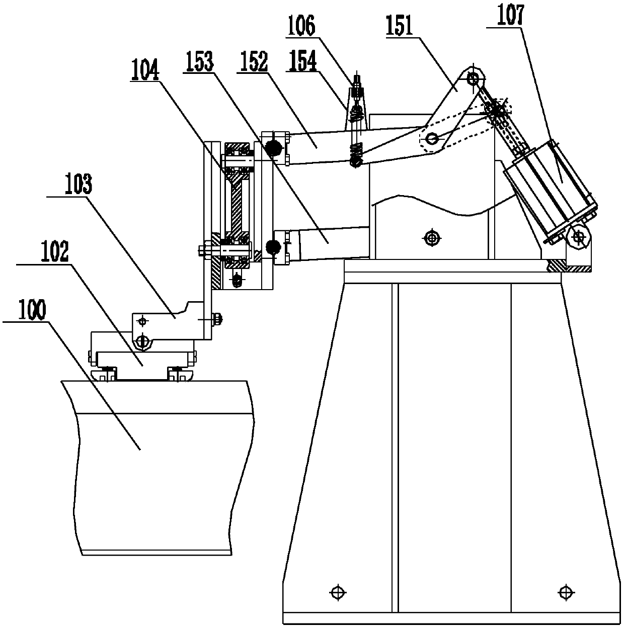
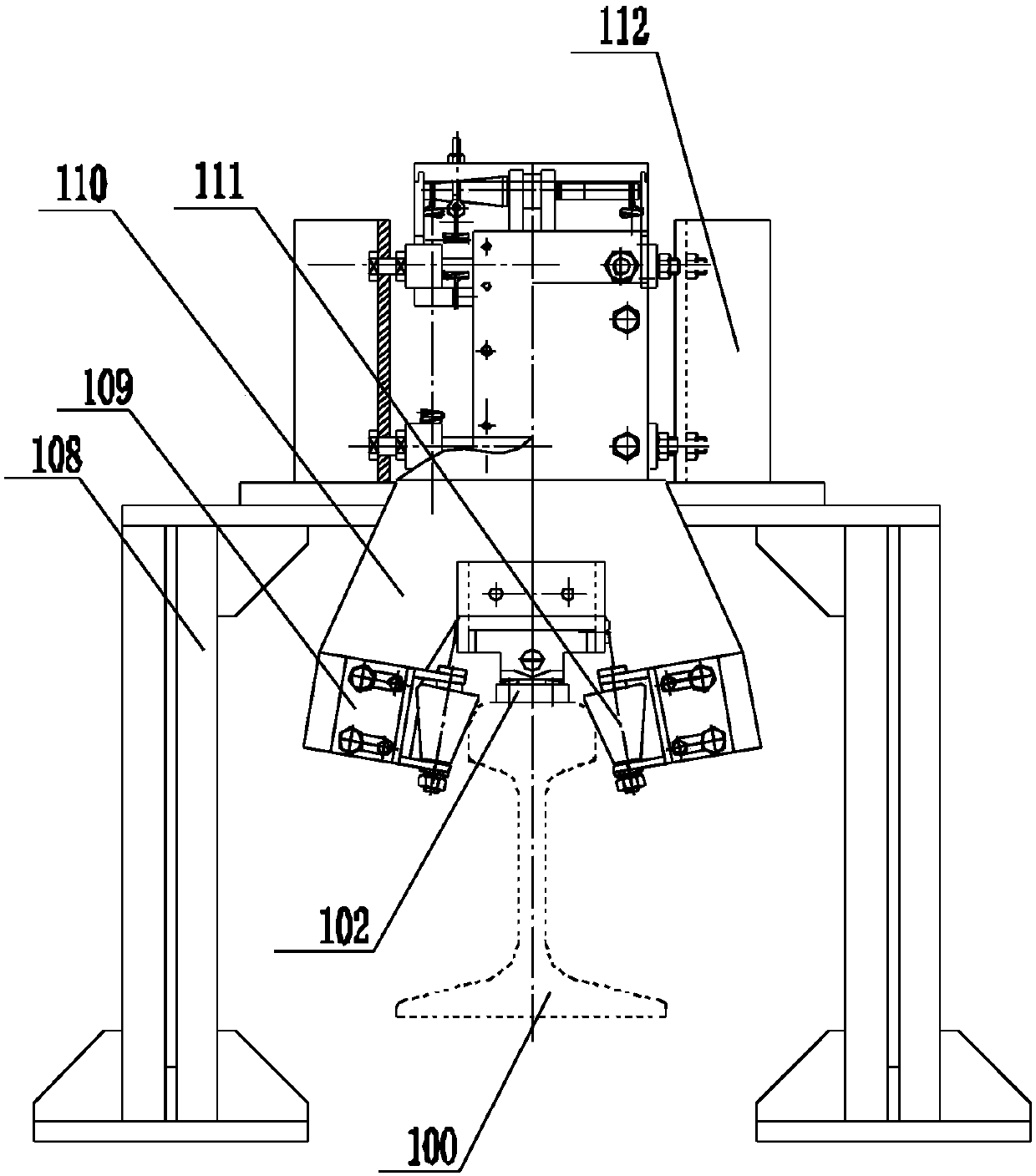
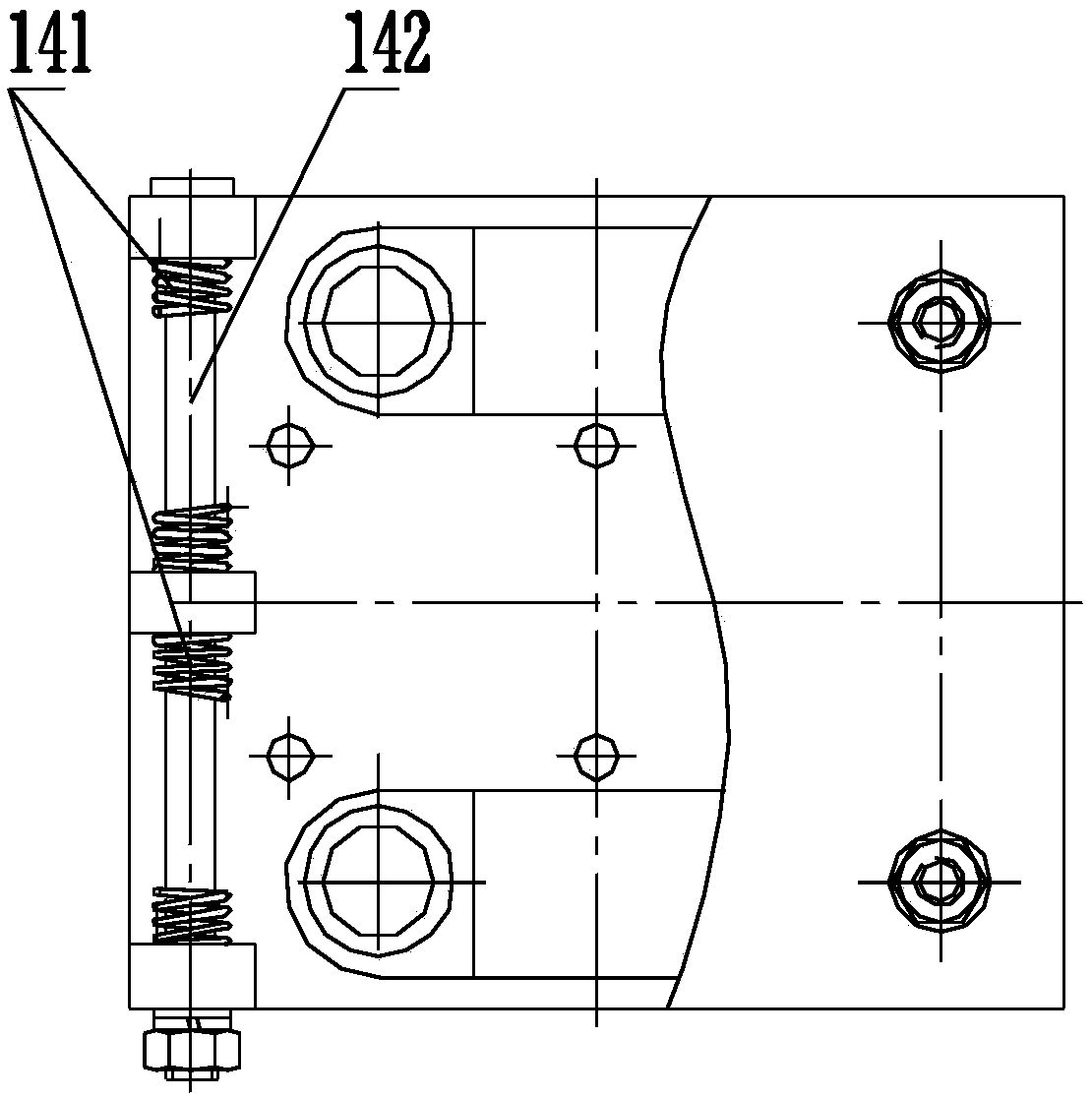
[0034] See Figure 1-Figure 10 , an ultrasonic flaw detection method for the upper arc and the lower jaw area on both sides of the rail head,

[0035] 1) Ultrasonic flaw detection of the lower jaw area of ​​rail 100, see Figure 5 , Image 6 :

[0036] An artificial flat-bottomed hole defect 113 is respectively set in the mandible area on both sides above the running center line of the rail 100 to be tested, Figure 5 is the flat-bottomed hole defect set on the left, Image 6 The flat-bottomed hole defect is set on the right; the artificial flat-bottomed hole defect 113 set in the lower jaw area on both sides of the rail 100 is a ∮2mm flat-bottomed hole, the allowable deviation of the flat-bottomed hole diameter: ±0.1mm; the depth is 9mm, the...


PUM


Abstract

The invention relates to an ultrasonic flaw detection method and a device for upper arcs and lower jaw areas on both sides of a rail head. Each upper arc and lower jaw area on both sides of the rail to-be-tested is provided with an artificial defect of flat-bottomed hole. Each lower jaw ultrasonic probe of the ultrasonic flaw detection device on the rail head is successively pressed down to both sides of the rail tread, and the lower jaw ultrasonic probe emits ultrasonic waves downward, the rail moves, to perform the flaw detection on the lower jaw of the rail, when the rail passes through twosets of the ultrasonic flaw detection device of lower jaw on the rail head. Each ultrasonic probe for upper arc is successively raised to the two lower jaw faces of the rail, and the two ultrasonic probes for the upper arcs emit ultrasonic waves upward, the rail moves, to perform the flaw detection on the upper arcs of the rail, when the rail passes through two sets of the ultrasonic flaw detection device of upper arcs on the rail head. According to the ultrasonic flaw detection method and the device for upper arcs and lower jaw areas on both sides of the rail head, the method and the devicehave the advantages that the detection of the blind spot of the ultrasonic flaw detection on the upper arcs and the lower jaw areas of the rail head is realized, and that the cross section of the railhead covered by ultrasonic wave >=90% is realized.

Description

technical field [0001] The invention belongs to the field of non-destructive flaw detection of rails, and in particular relates to an ultrasonic flaw detection method and device for the upper circular arc and the lower jaw area on both sides of the rail head. Background technique [0002] The upper arc area of ​​the rail head is in direct contact with the railway wheels, and the force between the wheels and rails is large and complex. The lower jaw area of ​​the rail head is frequently stretched and compressed under the action of the wheel pressure. The above two areas are prone to defects on the railway line. Area. The existing online automatic ultrasonic flaw detection technology for rails in China can only detect the core area of ​​the rail head. The two upper arcs and the lower jaw area of ​​the rail head are the flaw detection detection blind areas of the existing online automatic ultrasonic flaw detection technology for rails. The existing technology ultrasonic coverag...

Claims


Application Information

Patent Timeline
Patent Type & Authority Applications(China)
IPC IPC(8): G01N29/04G01N29/22B61K9/08
CPCB61K9/08G01N29/04G01N29/225G01N2291/0289G01N2291/2623
Inventor 马东杜斌刘鹤丁宁石帅王久鹏张巍尚剑洪李勇
Owner ANGANG STEEL CO LTD
Why Eureka
Try Eureka