Revit-based comprehensive pipe gallery BIM model creation method

A technology of comprehensive pipe gallery and pipe gallery, which is applied in the field of creation of BIM model based on Revit comprehensive pipe gallery, can solve the problems of large length of pipe gallery, high difficulty coefficient, and reduced work efficiency, so as to reduce computer memory, reduce difficulty coefficient, The effect of improving work efficiency

Pending Publication Date: 2019-04-02
CCCC FIRST HARBOR ENG +1
View PDF4 Cites 3 Cited by
  • Summary
  • Abstract
  • Description
  • Claims
  • Application Information

AI Technical Summary

Problems solved by technology

[0004] There are many specialties and complex pipelines in the comprehensive utility corridor. The traditional design method draws the plan and section diagram, which cannot fully display the complicated contents of the utility corridor, and it is easy to cause chain reaction errors when adjusting the pipeline. Therefore, the method of building a BIM model is often used. , in the traditional application of Revit software to create a three-dimensional model of the pipe gallery, due to the long pipe gallery, if the auxiliary structure model is directly constructed in the overall model of the pipe gallery, not only the difficulty factor is relatively large, but also the overall model will be in the process of creating It needs to consume a lot of computer memory, which will be very stuck in the modeling process and reduce work efficiency; and in the process of creating the pipeline model, due to the large length of the pipeline gallery and very tortuous, there are still pipeline models at the inflection point Difficult to connect at

Method used


Image

  • Revit-based comprehensive pipe gallery BIM model creation method

Examples


Embodiment 1

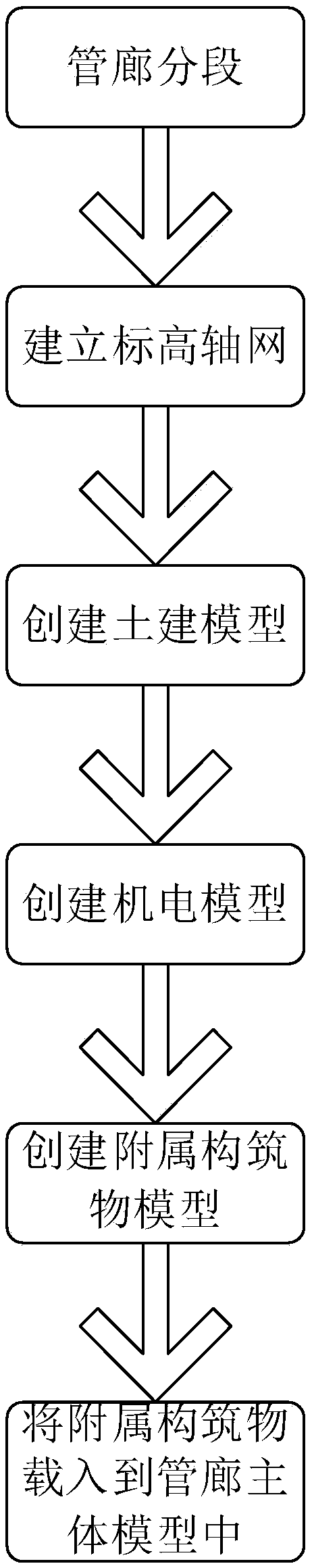
[0044] A method of creating a BIM model based on Revit comprehensive pipe gallery, the specific steps are as follows:

[0045] Step 1: Plan the main model of the pipe gallery, and use the slope change point of the pipe gallery, the node where the slope of the pipe gallery changes at the intersection of the pipe outlet and the pipe gallery, and the connection point between the standard section and the non-standard section of the pipe gallery as the segmentation points The principle of splitting the main model of the pipe gallery into pipe gallery modules;

[0046] Step 2, import the CAD drawing of the pipe gallery into the model file, use the CAD drawing as the base map to model the pipe gallery, and establish the elevation grid;

[0047] Step 3, construct the pipe gallery module model according to the split module in step 1 and the elevation grid created in step 2;

[0048] Step 4, sort out the auxiliary structures required for the pipe gallery, and use the pipe gallery modul...

Embodiment 2

[0061] A method of creating a BIM model based on Revit comprehensive pipe gallery, the specific steps are as follows:

[0062] Step 1: Plan the main model of the pipe gallery, and use the slope change point of the pipe gallery, the node where the slope of the pipe gallery changes at the intersection of the pipe outlet and the pipe gallery, and the connection point between the standard section and the non-standard section of the pipe gallery as the segmentation points The principle of splitting the main model of the pipe gallery into pipe gallery modules;

[0063] Step 2, import the CAD drawing of the pipe gallery into the model file, use the CAD drawing as the base map to model the pipe gallery, and establish the elevation grid;

[0064] Step 3, construct the pipe gallery module model according to the split module in step 1 and the elevation grid created in step 2;

[0065] Step 4, sort out the auxiliary structures required for the pipe gallery, and use the pipe gallery module ...


PUM


Abstract

The invention provides a Revit-based comprehensive pipe gallery BIM model creation method, and the method comprises the following specific steps of planning a pipe gallery main body model, and splitting the pipe gallery main body model into pipe gallery modules; importing the CAD drawing of the pipe gallery into the model file, and establishing an elevation axis network; constructing a pipe gallery module model; arranging accessory structures required to be established on the pipe gallery, and establishing a model of each accessory structure; and guiding each auxiliary structure into the pipegallery main body model and placing at the corresponding position of the pipe gallery main body, and attaching the top and the bottom of each wall body correspondingly to the pipe gallery top plate and the pipe gallery bottom plate respectively. According to the method for constructing the comprehensive pipe gallery BIM model, the difficulty coefficient of constructing the subsidiary structure model is reduced, the computer memory consumed when the subsidiary structure model is constructed is reduced, the jamming phenomenon is avoided, and the working efficiency is improved. In addition, the method for building the model effectively solves the problem that connection at the inflection point of the pipeline model is difficult.

Description

technical field [0001] The invention relates to the technical field of comprehensive utility gallery construction, in particular to a method for creating a BIM model based on Revit comprehensive utility gallery. Background technique [0002] The comprehensive pipe corridor is a structure and auxiliary facilities built underground to accommodate two or more types of urban engineering pipelines. Various engineering pipelines such as heating, water supply and drainage are integrated into one body, with special inspection ports, hoisting ports and monitoring systems, and the implementation of unified planning, unified design, unified construction and management is an important infrastructure and lifeline to ensure urban operation. [0003] BIM (Building Information Modeling) is based on 3D digital technology, and establishes a 3D data model based on various relevant information of construction projects, which is a digital expression of engineering entities and functional charact...

Claims


Application Information

Patent Timeline
IPC IPC(8): G06F17/50
CPCG06F30/13
Inventor 程海川王玉明谷守奎刘洁王官冰
Owner CCCC FIRST HARBOR ENG
Why Eureka
Try Eureka