Undisturbed switching-based multi-target running optimal control method of microgrid
A technology of non-disturbance switching and optimal control, which is applied in the fields of power electronics, communication and control
- Summary
- Abstract
- Description
- Claims
- Application Information
AI Technical Summary
Problems solved by technology
Method used
Image
Examples
Embodiment 1
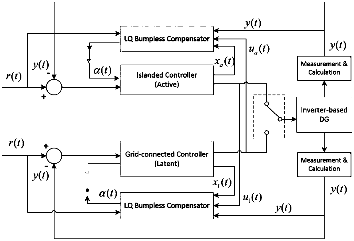
[0107] Switch from the island operation mode to the grid-connected operation mode, in this case, the sleep mode is the grid-connected operation mode, and the active mode is the island operation mode, the steps are as follows:
[0108]Step 1: First consider a general switched system model with two modes, and give a method for designing a mode-dependent bumpless switching compensation controller. Based on the optimal control theory of linear quadratic form, the design problem of mode-dependent disturbance-free compensation controller is transformed into the optimal control problem of linear quadratic form.
[0109] For a switching system operating in multiple modes, each operating mode has its own controller. For subsystem i, the state equation of the controller is as follows:
[0110]
[0111] where x(t)∈R n is the state vector of controller i, y(t)∈R q is the output of the controlled object, r∈R p is the reference signal to be tracked. A i B i C i D. i is the sys...
Embodiment 2
[0184] Switch from grid-connected operation mode to island operation mode
[0185] In this case, the sleep mode is the island operation mode and the active mode is the grid operation mode
[0186] This embodiment includes the following steps:
[0187] Step 1: First consider a general switched system model with two modes, and give a method for designing a mode-dependent bumpless switching compensation controller. Based on the optimal control theory of linear quadratic form, the design problem of mode-dependent disturbance-free compensation controller is transformed into the optimal control problem of linear quadratic form.
[0188] For a switching system operating in multiple modes, each operating mode has its own controller. For subsystem i, the state equation of the controller is as follows:
[0189]
[0190] where x(t)∈R n is the state vector of controller i, y(t)∈R q is the output of the controlled object, r∈R p is the reference signal to be tracked. A i B i C ...
PUM
 Abstract
Description
Claims
Application Information
 - R&D
- Intellectual Property
- Life Sciences
- Materials
- Tech Scout
- Unparalleled Data Quality
- Higher Quality Content
- 60% Fewer Hallucinations
Browse by: Latest US Patents, China's latest patents, Technical Efficacy Thesaurus, Application Domain, Technology Topic, Popular Technical Reports.
© 2025 PatSnap. All rights reserved.Legal|Privacy policy|Modern Slavery Act Transparency Statement|Sitemap|About US| Contact US: help@patsnap.com


