Permanent magnet synchronous motor control method based on second-order terminal slip form

A permanent magnet synchronous motor, terminal sliding mode technology, applied in motor control, motor generator control, electronic commutation motor control and other directions, can solve external disturbance, PI controller can not well suppress load disturbance, system uncertainty issues of sex

Active Publication Date: 2019-04-02
SOUTHEAST UNIV
View PDF7 Cites 24 Cited by
  • Summary
  • Abstract
  • Description
  • Claims
  • Application Information

AI Technical Summary

Problems solved by technology

However, as a multi-variable, strongly coupled nonlinear system, the performance of traditional linear control such as PI control is easily affected by system uncertainty and external disturbances. Secondly, when PI control is used, the pole of the motor will change with the change of speed , so the traditional PI control cannot achieve a high-performanc

Method used


Image

  • Permanent magnet synchronous motor control method based on second-order terminal slip form
  • Permanent magnet synchronous motor control method based on second-order terminal slip form
  • Permanent magnet synchronous motor control method based on second-order terminal slip form

Examples


Embodiment Construction

[0043] The present invention will be further described in detail below in conjunction with the accompanying drawings and specific preferred embodiments.

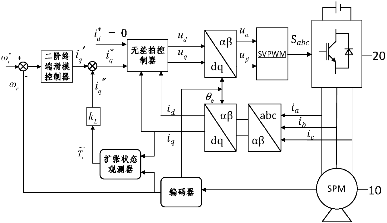
[0044] Such as figure 1 As shown, a permanent magnet synchronous motor control method based on the second-order terminal sliding mode includes the following steps.

[0045] Step 1, dq axis current i in the rotor coordinate system d and i q Acquisition: Measure and calculate the actual speed ω of the permanent magnet synchronous motor through the encoder (also known as the decoder, which is installed on the rotor shaft of the permanent magnet synchronous motor and outputs discrete position signals in real time) in each cycle r , the three-phase current i of the permanent magnet synchronous motor is collected by sampling circuits (such as current sensors, etc.) a i b and i c ; The three-phase current i a i b and i c Perform Clark transformation and Park transformation to obtain the dq axis current i in the rotor coordi...


PUM


Abstract

The invention discloses a permanent magnet synchronous motor control method based on a second-order terminal slip form. The method comprises the following steps that: S1: under a rotator coordinate system, obtaining dq shaft current id and iq; S2: obtaining a q shaft current given value iq'; S3: obtaining a load torque observation value; S4: after compensation, obtaining a q haft current given value iq<*>; S5: obtaining input voltage u[Alpha] and u[Beta] under an [Alpha] [Beta] coordinate system; and S6: adopting a space voltage vector pulse width modulation technology to convert the u[Alpha]and the u[Beta] obtained in S5 into an on-off signal used for controlling a three-phase inverter power device, and finally, driving the permanent magnet synchronous motor to operate. By use of the method, a current loop controller adopts a dead-beat controller, a speed loop adopts a two-order terminal slip form controller to realize the high-accuracy control of the permanent magnet synchronous motor, and therefore, the problem that the speed change range of the permanent magnet synchronous motor with small rotational inertia is large during load mutation or given revolving speed mutation can be solved.

Description

technical field [0001] The invention relates to the technical field of permanent magnet synchronous motors, in particular to a control method for permanent magnet synchronous motors based on a second-order terminal sliding mode. Background technique [0002] Due to its high efficiency, small size, and simple structure, permanent magnet synchronous motors have been widely used in aerospace, home appliances, electric vehicles and other fields in recent years. However, as a multi-variable, strongly coupled nonlinear system, the performance of traditional linear control such as PI control is easily affected by system uncertainty and external disturbances. Secondly, when PI control is used, the pole of the motor will change with the change of speed , so the traditional PI control cannot achieve a high-performance control characteristic in the full speed range. For general permanent magnet synchronous motors with small moment of inertia, when the load changes suddenly, the tradit...

Claims


Application Information

Patent Timeline
IPC IPC(8): H02P21/00H02P21/22H02P21/05
CPCH02P21/0007H02P21/05H02P21/22H02P2207/05
Inventor 樊英毛晨阳张秋实
Owner SOUTHEAST UNIV
Why Eureka
Try Eureka