Devices for far field bipolar ablation

A bipolar electrode and electrode technology, which is applied in the direction of application, medical equipment, surgical instrument parts, etc., can solve the problems of increasing the diameter of the element and limited treatment area

Inactive Publication Date: 2019-04-02
NEWURO
View PDF7 Cites 7 Cited by
  • Summary
  • Abstract
  • Description
  • Claims
  • Application Information

AI Technical Summary

Problems solved by technology

The problem with this technique mainly relates to the limited area that such electrodes can treat, so that if a large ablation area is required, a large number of electrodes must be used, resulting in many wires leading to it, which increases the diameter of the elements in the device

Method used


Image

  • Devices for far field bipolar ablation
  • Devices for far field bipolar ablation
  • Devices for far field bipolar ablation

Examples


Embodiment Construction

[0111] Far Field Bipolar Technology

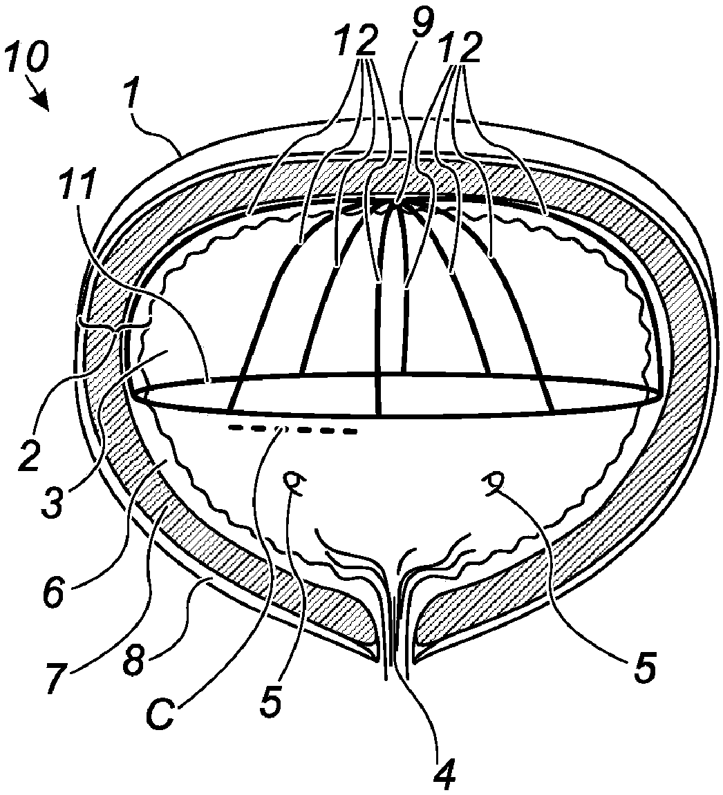
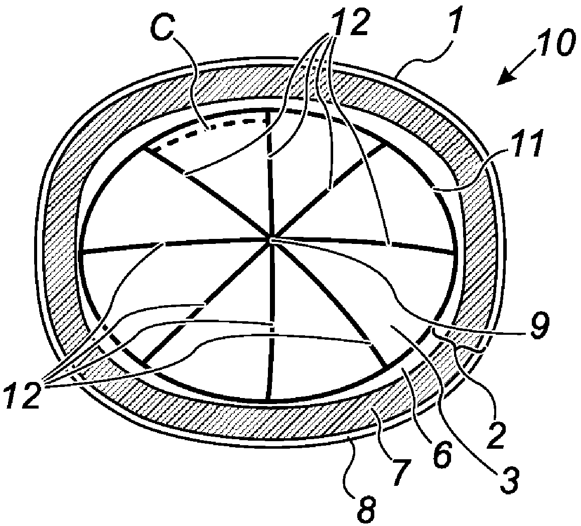
[0112] To address the needs outlined above, this disclosure describes a technique referred to herein as "far-field bipolar" ablation.

[0113] The technique is based on the use of bipolar electrodes or sets of electrodes with substantially equal and relatively large surface areas, which can be positioned at large distances from each other relative to the size of the electrodes, and in nearly opposite positions within the organ being treated . Thus, current flowing from one set of electrodes to the other can produce the same unipolar-like lesion on both electrode sets while sparing tissue between the electrodes.

[0114] To produce the desired effect, the distance between the electrodes should preferably be at least 10 times the relative dimension of the electrodes, which in the case of elongated electrodes may typically be the width of the electrode (or its diameter in the case of a wire electrode) ). In the applications described herei...


PUM


Abstract

The present disclosure describes devices and methods for treating disorders in a hollow body organ by ablating the tissue therein. At least one set of bipolar electrodes is deployed in the hollow bodyorgan to contact the inner wall of the organ. In the deployed position, each positive electrode is positioned in a location substantially opposite each negative electrode. The tissue contact areas ofthe positive and negative electrodes are substantially the same and the electrodes are separated from one another by a distance of at least 10 times the width of each of the electrodes. The electrodes thereby produce lesions that are substantially identical to one another and also similar to those produced with mono-polar electrodes. The electrodes are used to produce an ablation pattern that canelectrically isolate regions of the hollow body organ, thereby treating the disorder(s).

Description

[0001] cross reference [0002] This application claims the benefit of US Provisional Application No. 62 / 346,095, filed June 6, 2016, which is incorporated herein by reference. [0003] The subject matter of this application is related to that of the following co-pending patent applications: PCT Application No. PCT / IB2016 / 000953, filed June 10, 2016, and U.S. Patent Application No. 15 / 179,623, filed June 10, 2016, Both of the foregoing claim priority to US Provisional Patent Application No. 62 / 174,296, filed June 11, 2015, which applications are incorporated herein by reference. [0004] The subject matter of this application is also related to that of the following co-pending patent application: PCT Application No. PCT / IB2014 / 003083 filed on November 25, 2014, which claims 14 / 519,933, a continuation of PCT Application Serial No. PCT / IB2013 / 001203, filed April 19, 2013, which was filed on April 19, 2013, and which PCT Application Serial No. PCT / IB2013 / 001203 claims the benefi...

Claims


Application Information

Patent Timeline
Patent Type & Authority Applications(China)
IPC IPC(8): A61B18/14A61B18/20A61B18/00
CPCA61B18/1485A61B18/1492A61B18/22A61B2018/0016A61B2018/00166A61B2018/00214A61B2018/00255A61B2018/00267A61B2018/00517A61B2018/00577A61B2018/00946A61B2018/1465A61B2018/1467A61B2018/1475A61B1/307A61B2018/0022A61B2018/00494A61B2018/00559A61B2018/00875A61B2018/0212A61B2018/144A61M2210/1085A61N1/32
Inventor 罗杰·A·斯特恩杰罗姆·杰克逊本杰明·王欧姆瑞·本-以斯拉伊扎克·阿韦尔尼利奥尔·阿夫涅里
Owner NEWURO
Why Eureka
Try Eureka