Lighting fixture for vehicle

A technology for lamps and vehicles, which is applied to headlights, vehicle parts, optical elements for changing the spectral characteristics of emitted light, etc., and can solve the problems of driver's sense of incongruity, incongruity, and lowering

Active Publication Date: 2019-04-02
ICHIKOH IND LTD
View PDF6 Cites 5 Cited by
  • Summary
  • Abstract
  • Description
  • Claims
  • Application Information

AI Technical Summary

Problems solved by technology

[0002] Patent Document 1 discloses a vehicle headlamp capable of performing Adaptive Driving Beam (Adaptive Driving Beam) control that changes the light distribution pattern of the high beam. If the light source in the central part of the light distribution pattern is turned off by the presence of other vehicles, the high beam light distribution pattern is formed in a state of being roughly equally divided in the left and right directions, which will give the driver a sense of incongruity. feeling of incongruity

Method used


Image

  • Lighting fixture for vehicle
  • Lighting fixture for vehicle
  • Lighting fixture for vehicle

Examples


no. 1 approach

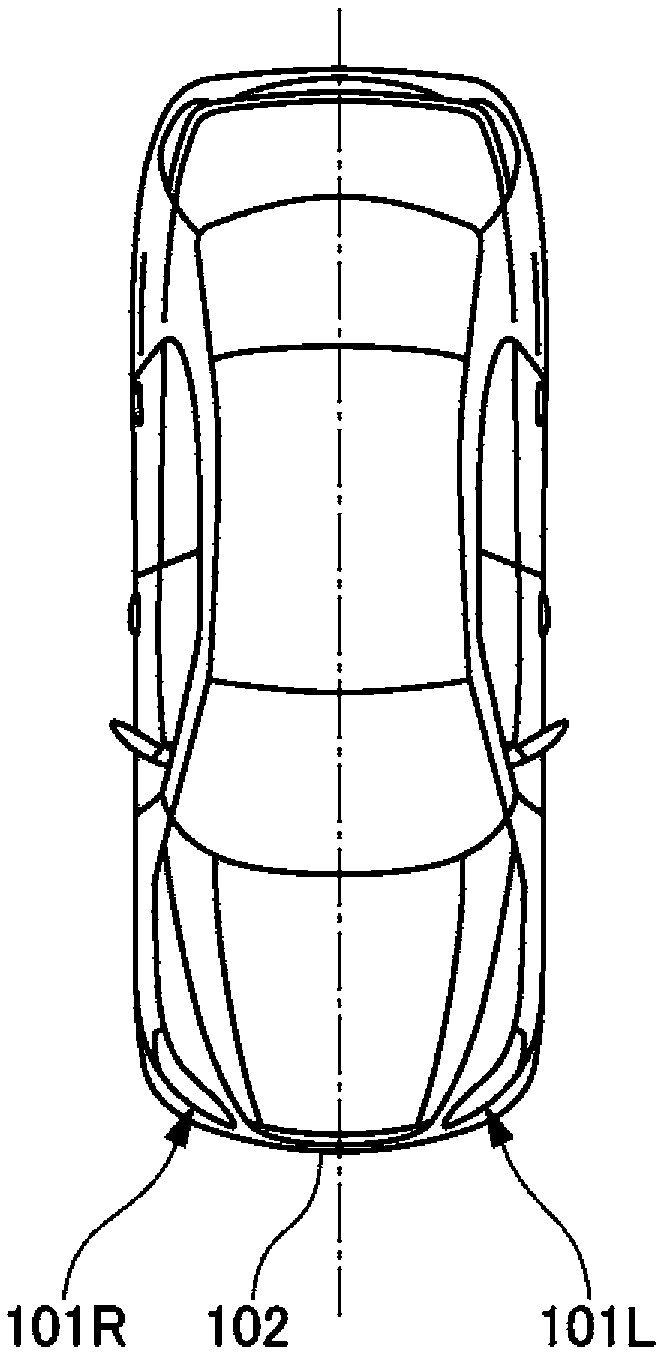
[0037] The vehicle lamp of this embodiment includes a case (not shown) facing the vehicle front side and an outer lens (not shown) attached to the case so as to cover the opening. Configured with lamp unit 10 (refer to figure 2 )Wait.

[0038] In addition, in the description of the lamp unit 10 below, parts not particularly described are common to left and right vehicle lamps.

[0039] (lamp unit)

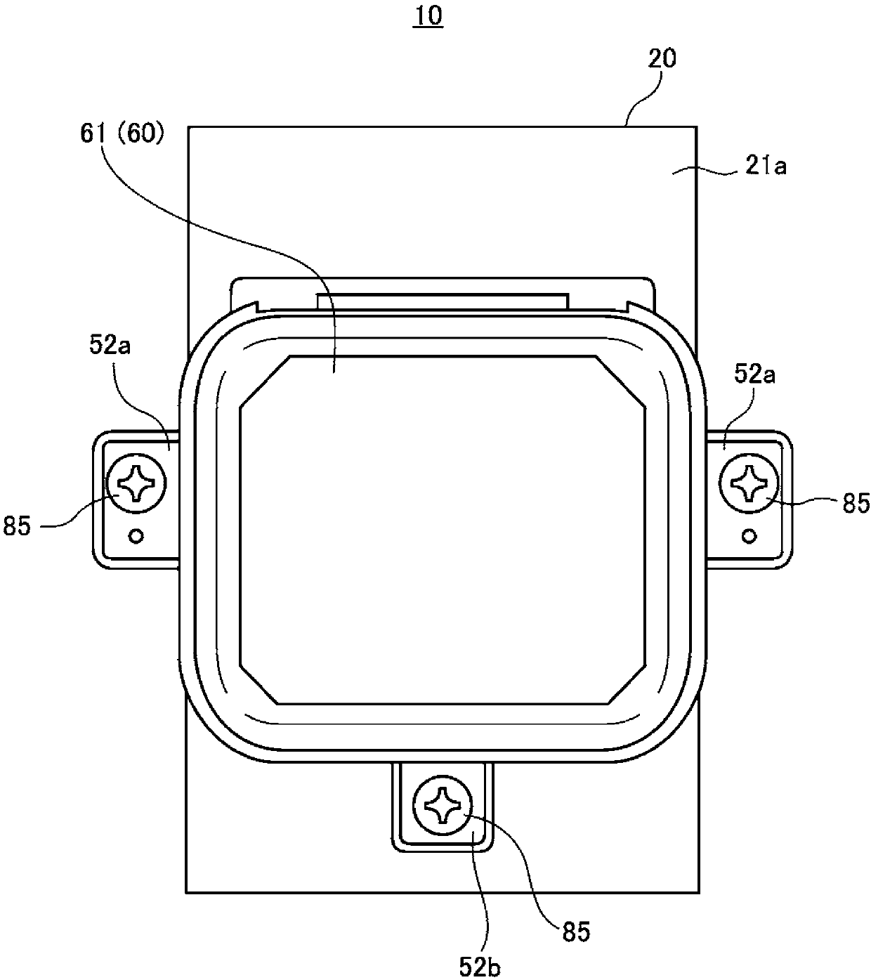
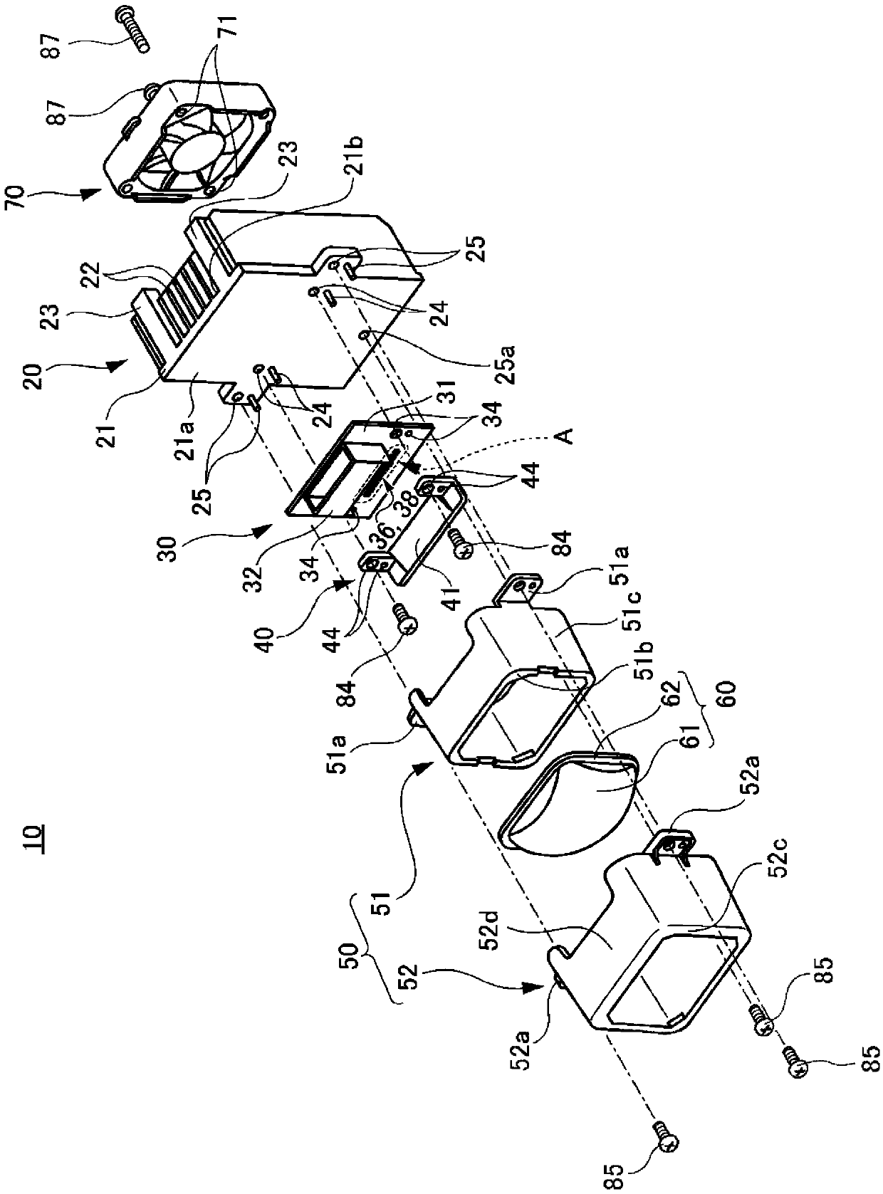
[0040] figure 2 is a plan view of the lamp unit 10 viewed from the front side, image 3 It is an exploded perspective view of the lamp unit 10 .

[0041] As will be described later, the lamp unit 10 is a variable light distribution high beam light distribution unit having a plurality of light emitting parts (the first light emitting part 36 and the second light emitting part 38 ( refer to Figure 4 )) light sources 30 arranged side by side in the horizontal direction (refer to image 3 ), according to the positional relationship with the vehicle in front and the oncoming veh...

no. 2 approach

[0162] The lamp unit 10 of the first embodiment is a lamp unit for high-beam light distribution. However, the vehicle lamp according to the embodiment of the present invention is not limited to having such a lamp unit for high-beam light distribution. A lamp unit 10 capable of switching between a high-beam light distribution pattern and a low-beam light distribution pattern as described in the embodiment.

[0163] Figure 8 is a cross-sectional view showing the lamp unit 10 used in the vehicle lamp according to the second embodiment, Figure 9 It is a plan view of the lamp unit 10 of the second embodiment seen from the front side.

[0164] also, Figure 9 The illustration of the lens 60 is omitted in FIG.

[0165] Also in the lamp unit 10 of the second embodiment, the basic component configuration is similar to that of the first embodiment, and the description of the same points as those of the first embodiment may be omitted.

[0166] Such as Figure 8 As shown, the lamp...


PUM


Abstract

In order to provide a lighting fixture for vehicle with which it is possible to form a more suitable high beam flux distribution pattern while taking into consideration part costs, this lighting fixture for vehicle is provided with a light source and a lens, the light source comprising a substrate, a first light-emitting part having a first base substrate provided on the substrate, and a pluralityof second light-emitting parts positioned on the outside of the first light-emitting part in the horizontal direction and having a second base substrate provided on the substrate. The first light-emitting part comprises a pair of first light-emitting chip parts provided on the first base substrate with a first separating part interposed therebetween. Each of the plurality of second light-emittingparts is equipped with a second light-emitting chip part obtained by covering, with a phosphor, a second light-emitting chip mounted on a second base substrate with the light-emitting layer side as the second base substrate side. The pair of first light-emitting chip parts comprise a first light-emitting chip mounted on the first base substrate, and a phosphor that covers the first light-emittingchip. In the first light-emitting part, the first separating part is positioned on a perpendicular axis that passes along the lens optical axis, and the first separating part has a smaller width thanthe width separating the first light-emitting part and the second light-emitting part.

Description

technical field [0001] The present invention relates to lamps for vehicles. Background technique [0002] Patent Document 1 discloses a vehicle headlamp capable of performing Adaptive Driving Beam (Adaptive Driving Beam) control that changes the light distribution pattern of the high beam. If the light source in the center of the light distribution pattern is turned off by the presence of other vehicles, the high beam light distribution pattern is formed in a state of being roughly equally divided in the left and right directions, which will give the driver a sense of incongruity. A feeling of incongruity. [0003] prior art literature [0004] patent documents [0005] Patent Document 1: Japanese Patent Laid-Open No. 2013-20709 Contents of the invention [0006] The problem to be solved by the invention [0007] In addition, in the case of performing ADB control, control is performed so that the light from each light emitting unit arranged in the horizontal direction...

Claims


Application Information

Patent Timeline
Patent Type & Authority Applications(China)
IPC IPC(8): F21S41/25F21V9/35F21W102/00F21Y115/10
CPCH01L33/50H01L33/58H01L25/0753F21S41/143F21S41/151F21S41/25F21S41/192F21S41/295F21S41/321F21S41/663F21S45/47F21S45/43F21S41/148F21S41/255H01L33/502H01L33/32H01L33/06H01L33/0025H01L33/145
Inventor 大久保泰宏
Owner ICHIKOH IND LTD
Why Eureka
Try Eureka