motor

A technology of motors and bearings, applied in the field of motors, can solve problems such as damage and achieve the effect of suppressing damage

Active Publication Date: 2020-12-08
NIDEC CORP
View PDF5 Cites 0 Cited by
  • Summary
  • Abstract
  • Description
  • Claims
  • Application Information

AI Technical Summary

Problems solved by technology

In such a motor, when the lead wire is connected to the terminal, due to the downward load applied to the terminal holding part, excessive force may be applied to the connecting part of the bracket bottom and the terminal holding part, etc., resulting in damage.

Method used


Image

  • motor
  • motor
  • motor

Examples


Embodiment Construction

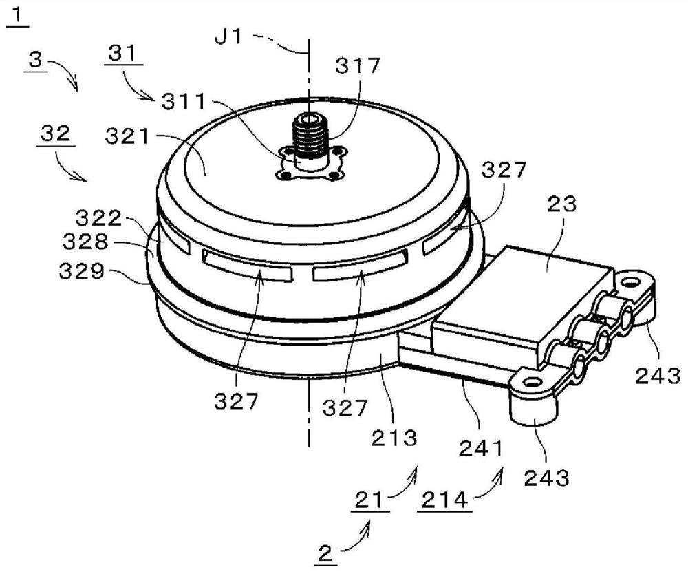
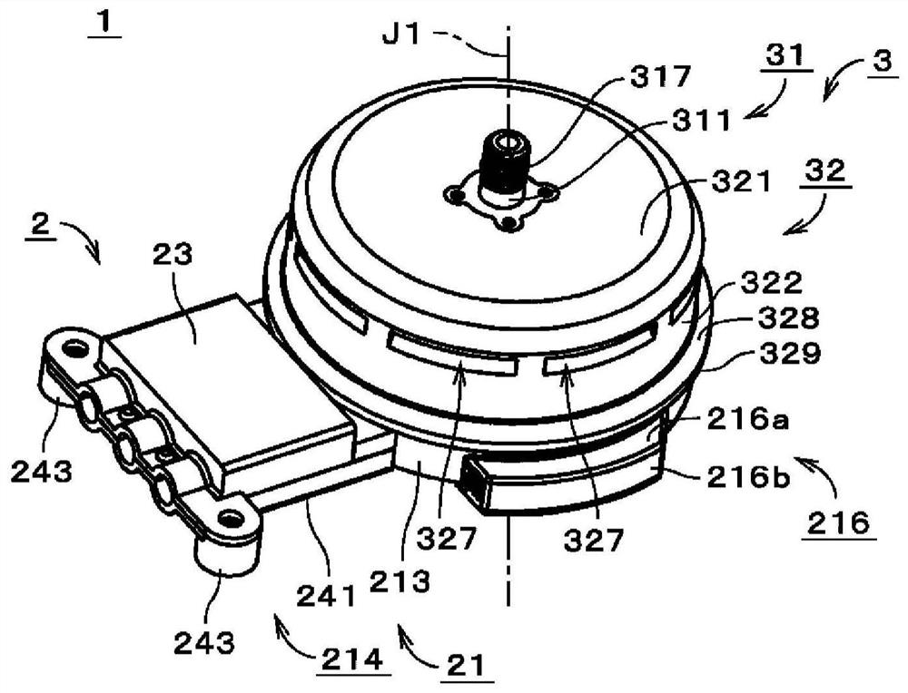
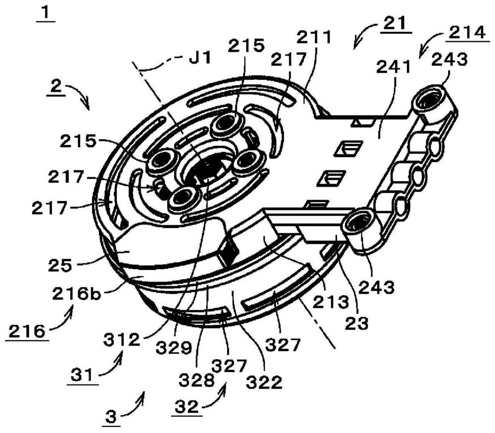
[0021] figure 1 It is a perspective view showing the appearance of a motor 1 according to an exemplary embodiment of the present invention. The motor 1 is an outer rotor type brushless motor. The motor 1 is used, for example, to rotate an impeller in an axial fan. figure 2 and image 3 is from with figure 1 Perspective views of the motor 1 viewed from different directions. Figure 4 is a longitudinal sectional view of the motor 1 . exist Figure 4 In , the parallel oblique lines in the section of the detail part are omitted. In addition, in Figure 4 In , the structure on the inner side of the cross section and a part of the outer surface of the motor 1 are also drawn together.

[0022] In this manual, the Figure 4 The upper side in the direction of the central axis J1 of the motor 1 is simply referred to as "upper side", and the lower side is simply referred to as "lower side". The upper and lower sides in this specification do not mean the upper and lower sides i...


PUM


Abstract

The motor has: a shaft centered on a central axis along the up-down direction; a bearing mechanism that rotatably supports the shaft; an armature located radially outside the bearing mechanism; and a bracket fixed with The bearing mechanism and the armature; and a covered cylindrical rotor connected to the shaft. The bracket has a bracket bottom that covers a lower side of the armature, and a terminal holding portion that extends radially outward from an outer peripheral portion of the bracket bottom. The terminal holding part has: a plate-shaped holding part main body connected to the outer peripheral part of the bottom of the bracket; terminals arranged on the upper surface of the holding part main body and connected to lead wires from an external power supply; A portion protrudes downward from the lower surface of the holding portion main body at the same position in the radial direction as the terminal or at a position radially outer than the terminal.

Description

technical field [0001] This invention relates to motors. Background technique [0002] Conventionally, in motors, in order to facilitate the connection of a plurality of coils of an armature to an external power source, metal bus bars are sometimes used. For example, in the motor disclosed in Japanese Laid-Open Publication No. 2007-202263, a part of the bus bar protrudes radially outward from the motor, and a power line from an external power source is connected to the protruding portion. [0003] However, in motors, terminals for connecting lead wires from an external power source are sometimes provided on terminal holding portions extending radially outward from the bottom of the bracket covering the lower side of the armature. In such a motor, when a lead wire is connected to the terminal, due to a downward load applied to the terminal holding portion, excessive force may be applied to the connection portion between the bottom of the bracket and the terminal holding port...

Claims


Application Information

Patent Timeline
IPC IPC(8): H02K5/22
CPCH02K5/225H02K3/522H02K2203/09H02K5/1737
Inventor 牧野祐辅
Owner NIDEC CORP
Why Eureka
Try Eureka