Jet machining device and surface machining method for object to be processed
A technology for a workpiece and a processing device, which is applied in the field of damaged blasting equipment, can solve the problems of reduced surface processing quality and unstable spraying state of the workpiece, and achieves the effect of suppressing damage.
- Summary
- Abstract
- Description
- Claims
- Application Information
AI Technical Summary
Problems solved by technology
Method used
Image
Examples
no. 1 approach
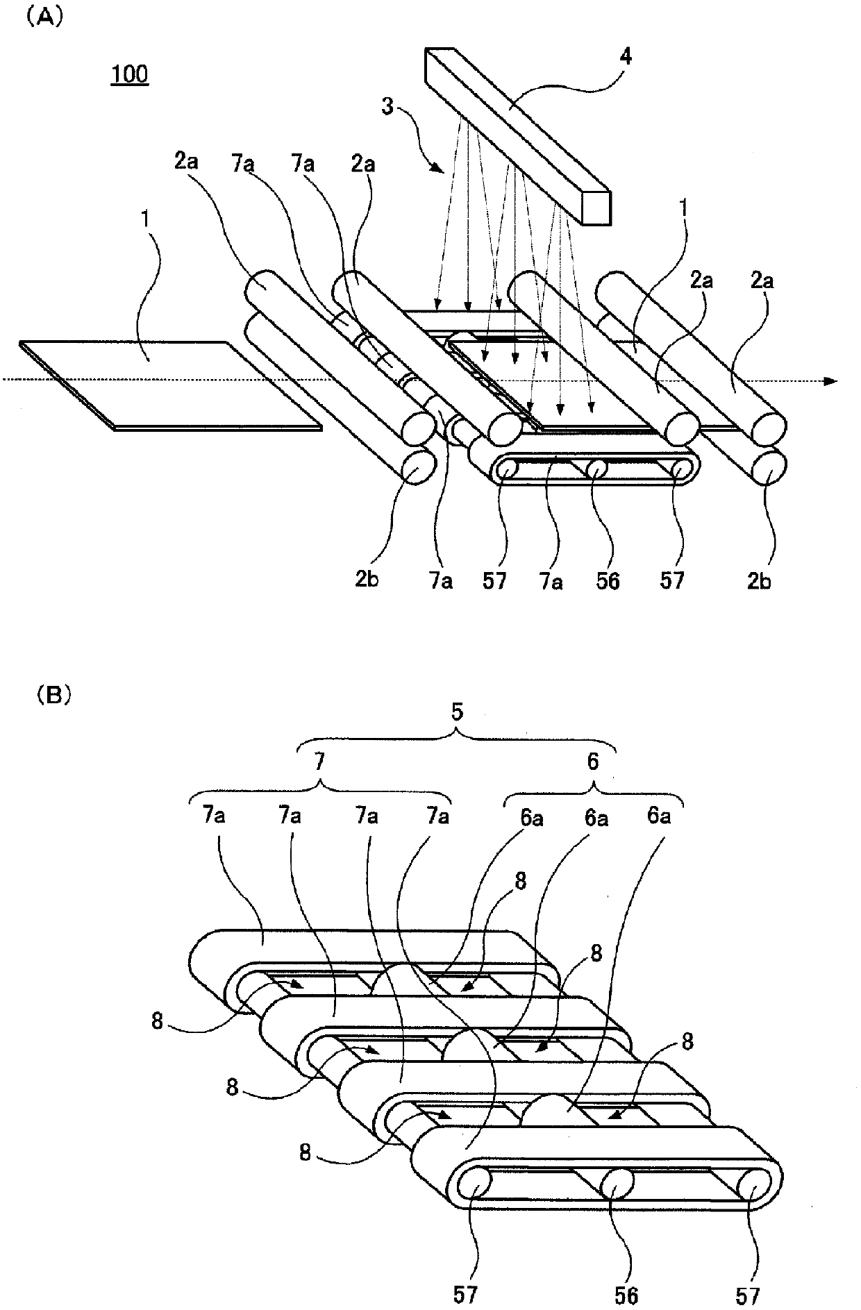
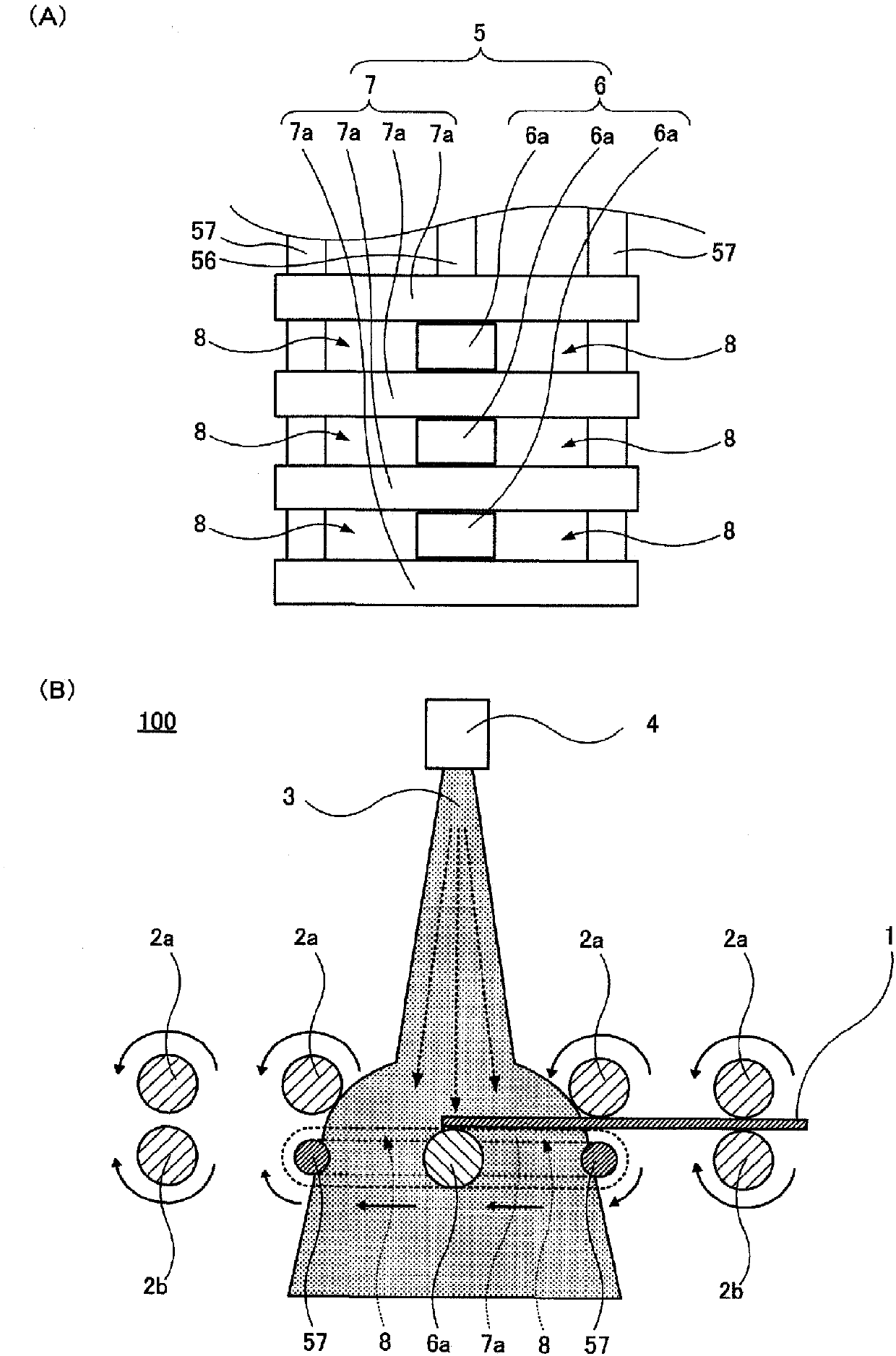
[0059] exist figure 1 of (A), figure 1 of (B), figure 2 of (A), figure 2 In (B), the spray processing apparatus 100 which concerns on 1st Embodiment is shown. in, figure 1 (A) is a perspective view of the spray processing device 100 . figure 1 (B) is a perspective view of main parts showing the rotary support 5 of the blasting processing apparatus 100 . figure 2 (A) is a main-part plan view showing the rotary support 5 of the spray processing apparatus 100 . figure 2 (B) is a sectional view of the spray processing apparatus 100 .
[0060] The spray processing apparatus 100 includes an upper roller 2 a and a lower roller 2 b as a workpiece conveying mechanism for conveying the workpiece 1 . The upper roller 2a and the lower roller 2b are driven to rotate by a drive mechanism (not shown), and convey the workpiece 1 . In addition, in figure 1 (A)~ figure 2 In (B), four upper rolls 2a and two lower rolls 2b are shown in the figure, but the number of upper rolls...
no. 2 approach
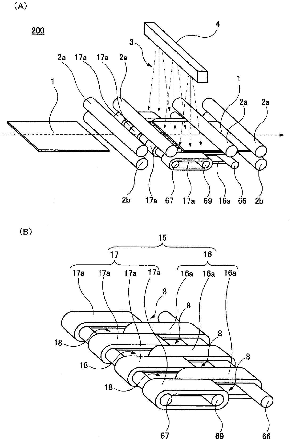
[0077] exist image 3 (A), (B), Figure 4 In (A) and (B), the spray processing apparatus 200 which concerns on 2nd Embodiment is shown. in, image 3 (A) is a perspective view of the spray processing device 200 . image 3 (B) is a perspective view of main parts showing the rotary support 15 of the blast processing apparatus 200 . Figure 4 (A) is a main-part plan view showing the rotary support 15 of the spray processing apparatus 200 . Figure 4 (B) is a sectional view of the spray processing apparatus 200 .
[0078] exist figure 1 (A)~ figure 2 In the spray processing apparatus 100 according to the first embodiment shown in (B), the rotary support 5 is formed by combining the first rotary support 6 including three rollers 6 a and the first rotary support 6 including four belts 7 a. Two rotary supports 7 are formed.
[0079] In the spray processing apparatus 200, instead, the rotary support 15 is comprised by combining the 1st rotary support 16 provided with the three ...
no. 3 approach
[0091] Figure 5 (A), (B) have shown the blast processing apparatus 300 which concerns on 3rd Embodiment. in, Figure 5 (A) is a main part perspective view which shows the rotary support 25 of the blast processing apparatus 300. FIG. Figure 5 (B) is a main-part plan view showing the rotary support 25 of the blasting machine 300 .
[0092] exist figure 1 (A)~ figure 2 In the spray processing apparatus 100 according to the first embodiment shown in (B), the rotary support 5 is composed of a first rotary support 6 including three rollers 6 a and a second rotary support 6 including four belts 7 a. Type support 7 constitutes.
[0093] In the spray processing apparatus 300, instead, the rotary support 25 is comprised of the 1st rotary support 26 provided with the one wide roll 26a, and the 2nd rotary support 27 which provided the two wide belts 27a.
[0094] The roller 26a is fixed to the shaft 76 and driven to rotate by the shaft 76 . In addition, the shaft 76 is fixed to...
PUM
 Abstract
Description
Claims
Application Information
 - R&D
- Intellectual Property
- Life Sciences
- Materials
- Tech Scout
- Unparalleled Data Quality
- Higher Quality Content
- 60% Fewer Hallucinations
Browse by: Latest US Patents, China's latest patents, Technical Efficacy Thesaurus, Application Domain, Technology Topic, Popular Technical Reports.
© 2025 PatSnap. All rights reserved.Legal|Privacy policy|Modern Slavery Act Transparency Statement|Sitemap|About US| Contact US: help@patsnap.com


