Eureka AIR delivers breakthrough ideas for toughest innovation challenges, trusted by R&D personnel around the world.

Sanitary washing device

A technology for sanitary cleaning and valve unit, which is applied to valve devices, water supply devices, sanitary equipment, etc., can solve problems such as easy breakage, and achieve the effect of suppressing breakage

Active Publication Date: 2021-01-05
TOTO LTD
View PDF8 Cites 0 Cited by
  • Summary
  • Abstract
  • Description
  • Claims
  • Application Information

AI Technical Summary

Problems solved by technology

[0003] However, if the valve unit is made of a relatively hard material, there is a problem that when the water in the valve unit expands due to freezing, the valve unit cannot be deformed to correspond to the expansion of the water and is easily damaged.

Method used


Image

  • Sanitary washing device
  • Sanitary washing device
  • Sanitary washing device

Examples


Embodiment Construction

[0046] Hereinafter, embodiments of the present invention will be described with reference to the drawings. In addition, in each drawing, the same reference numerals are assigned to the same components, and detailed description thereof will be appropriately omitted.

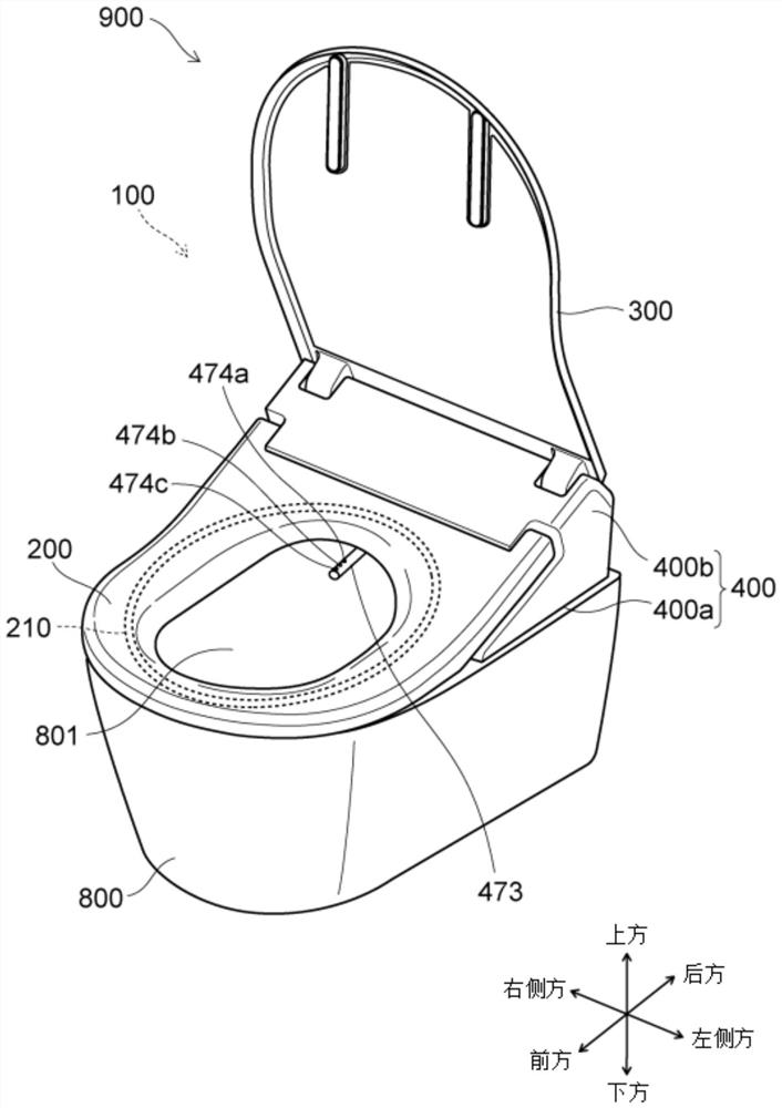
[0047] figure 1 It is a perspective view which schematically shows the toilet apparatus provided with the sanitary washing apparatus concerning embodiment.

[0048] Such as figure 1 As shown, the toilet flushing device 900 includes a western-style toilet (toilet) 800 and a sanitary washing device 100 disposed thereon. The sanitary washing device 100 has a case 400 , a toilet seat 200 , and a toilet cover 300 . The toilet seat 200 and the toilet cover 300 are pivotally supported by the casing 400 so as to be freely openable and closable. The case 400 has a lower shell plate 400a and an upper shell 400b, and accommodates functional parts such as the nozzle 473 in the inner space. A heater 210 for heating the to...


PUM


Abstract

The invention provides a sanitary washing device which can prevent a valve unit from being damaged due to freezing even if the valve unit is made of harder materials. The sanitary washing device is provided with a nozzle that discharges water to a part of a human body; a valve unit which is arranged on a pipeline between the water supply source and the nozzle and is provided with an electromagnetic valve; a housing that houses the nozzle and the valve unit; and a toilet seat rotatably and pivotally supported by the housing and having a heater therein, and the sanitary washing device is characterized in that at least a part of the valve unit is disposed below the toilet seat.

Description

technical field [0001] Aspects of the present invention generally relate to a sanitary washing device. Background technique [0002] In sanitary washing apparatuses, a technique is known in which a valve unit including a solenoid valve and the like is provided on a pipeline for supplying water from a water supply source to a nozzle. Since the valve unit is supplied with water at inlet pressure from a water supply source, high strength is required. Therefore, the valve unit is usually made of a relatively hard material. [0003] However, if the valve unit is made of a relatively hard material, there is a problem that when the water in the valve unit expands due to freezing, the valve unit cannot be deformed to correspond to the expansion of the water and is easily damaged. [0004] patent documents [0005] Patent Document 1: Japanese Patent Laid-Open No. 2002-294801 Contents of the invention [0006] The present invention is based on the recognition of such a problem, ...

Claims


Application Information

Patent Timeline
IPC IPC(8): E03D9/08E03D9/00E03D9/16E03D5/10E03D1/30
CPCE03D9/08E03D9/00E03D9/16E03D5/10E03D1/30A47K13/305F16K11/24F16K31/02B01D35/02F24H1/10
Inventor 山村早希山川刚志持田真之
Owner TOTO LTD
Why Eureka
Eureka Blog
Learn More