Optical module

A technology of optical modules and optical components, applied in the field of optical modules, can solve problems such as glass substrate damage, lower positioning accuracy, and deformation of positioning pins, and achieve the effect of suppressing damage

Inactive Publication Date: 2015-05-27
FUJIKURA LTD
View PDF10 Cites 0 Cited by
  • Summary
  • Abstract
  • Description
  • Claims
  • Application Information

AI Technical Summary

Problems solved by technology

Therefore, if the positioning pins come into contact with the damaged layer of the positioning hole of the glass substrate, the damaged layer may receive stress from the pins, and the glass substrate may be damaged starting from minute unevenness or cracks.
Alternatively, if there are minute irregularities in the positioning hole, the positioning pin may be deformed and the positioning accuracy may be lowered.

Method used


Image

  • Optical module
  • Optical module
  • Optical module

Examples


no. 1 Embodiment approach

[0044]

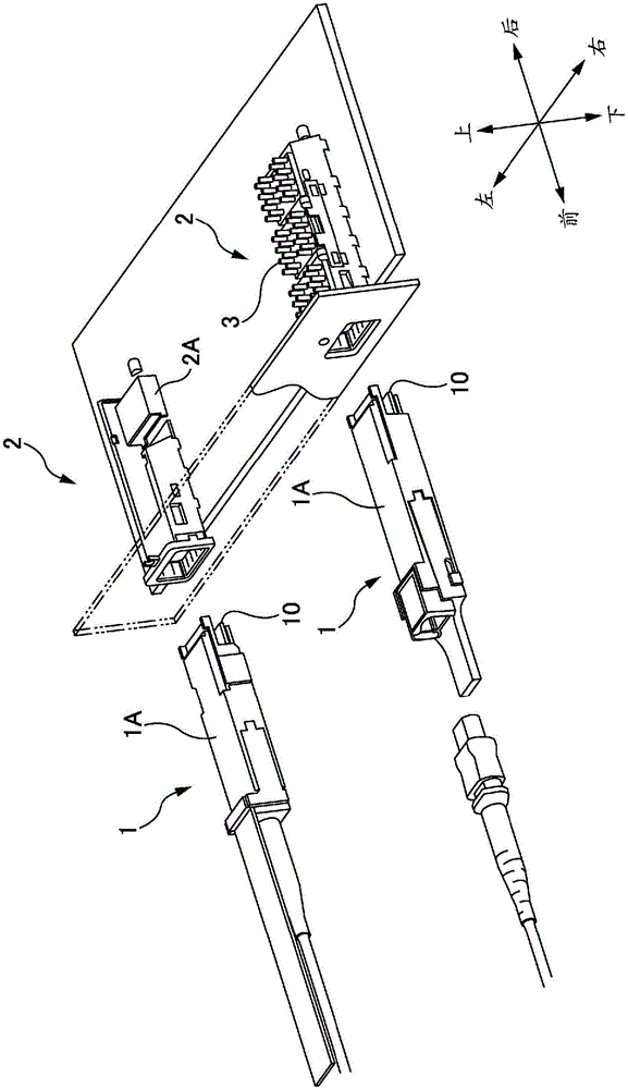
[0045] figure 1 It is an explanatory diagram of a pluggable optical transceiver. In addition, although a device including both an optical transmitter and an optical receiver is sometimes referred to as an optical transceiver, a device including only one of them is also referred to as an optical transceiver here. The pluggable optical transceiver in the figure is a QSFP type (QSFP: Quad Small Form Factor Pluggable) device specified by MSA (Multi Source Agreement). The pluggable optical transceiver has an optical module 1 and a cover 2 .

[0046] Two kinds of light modules 1 are depicted in the figure. As shown in the figure, optical fibers (including cords) may be fixed to the optical module 1 , or may be detachable from the optical module 1 . One of the two covers 2 in the figure is drawn by removing the heat sink 3 and cutting a part so that it can be observed.

[0047] In the description below, if figure 1Front and rear, top and bottom, and left and right are...

no. 2 Embodiment approach

[0110] Figure 11 It is explanatory drawing of 2nd Embodiment.

[0111] In the aforementioned first embodiment, the protective film 24 is formed along the edge of the positioning hole 23 , and the protective film 24 is not formed at the bottom of the positioning hole 23 . In contrast, in the second embodiment, the protective film 24 is formed on the inner surface of the positioning hole 23 , and the protective film 24 is also formed on the bottom of the positioning hole 23 .

[0112] Since the damaged layer when forming the positioning hole 23 is not only formed on the edge of the positioning hole 23, but also largely formed on the inner surface of the positioning hole 23, by forming the protective film 24 on the inner surface of the positioning hole 23, it is possible to further suppress the damage of the glass substrate. 20 for breakage.

[0113] However, in the second embodiment, since the protective film 24 is also formed on the bottom of the positioning hole 23, it is n...

no. 3 Embodiment approach

[0115] Figure 12 It is explanatory drawing of 3rd Embodiment.

[0116] In the aforementioned first embodiment, the protective film 24 is formed together with the passivation film 25 . Therefore, the protective film 24 has the same material as the passivation film 25 and the same thickness as the passivation film 25 . On the other hand, the protective film 26 of the third embodiment has a material different from that of the passivation film 25 .

[0117] According to the third embodiment, since the protective film 26 can be formed independently of the passivation film 25, the material and film thickness can be freely set. Therefore, the material of the protective film 26 can be selected regardless of the adhesiveness with the glass substrate side electrode 22 .


PUM

PropertyMeasurementUnit
The inside diameter ofaaaaaaaaaa
Linear expansion rateaaaaaaaaaa

Abstract

[Problem] To suppress breakage of a glass substrate having an alignment hole formed therein, and deformation of an alignment pin. [Solution] This optical module is characterized by: being provided with an optical component having an alignment pin formed thereon, and a glass substrate, which has a photoelectric conversion element mounted thereon, and which is capable of transmitting light emitted from the photoelectric conversion element or light to be received by means of the photoelectric conversion element, said glass substrate having an alignment hole formed therein; and having the glass substrate and the optical component aligned with each other by having the alignment pin fitted in the alignment hole through a protection film such that the protection film is in contact with the alignment hole and the alignment pin.

Description

technical field [0001] The present invention relates to optical modules. Background technique [0002] In the field of high-speed optical communication using optical fibers, optical transceivers are used as means for converting electrical signals and optical signals to each other. The specifications (shape, size, pin assignment, etc.) of the pluggable optical transceiver are standardized by the MSA (Multi Source Agreement) stipulated by an industry group dealing with optical transceivers. According to the above-mentioned pluggable optical transceiver, the cover is provided on the main board on the communication device side (host side), and the optical module incorporating the photoelectric conversion element and the circuit board is detachably inserted into the cover. When the optical module is inserted into the cover, the circuit board in the optical module can be electrically / mechanically connected to the electrical interface connector in the cover. Thereby, the optical ...

Claims


Application Information

Patent Timeline
IPC IPC(8): G02B6/42
CPCG02B6/4214G02B6/4292G02B6/4284G02B6/4246G02B6/428G02B6/4259G02B6/423
Inventor 松丸幸平山本敏中里弘人
Owner FUJIKURA LTD
Why Eureka
Try Eureka