Eureka AIR delivers breakthrough ideas for toughest innovation challenges, trusted by R&D personnel around the world.

Jaw with reinforcement device

A technology of booster device and screw shaft, which is applied in the vise, positioning device, transmission device, etc., can solve the problems of damage, rapid wear, deformation, etc., and achieve the effect of suppressing damage

Active Publication Date: 2007-07-25
TSUDAKOMA KOGYO KK
View PDF3 Cites 0 Cited by
  • Summary
  • Abstract
  • Description
  • Claims
  • Application Information

AI Technical Summary

Problems solved by technology

Therefore, the guide pins as the fixing parts of the stop ring, the rotating propulsion part and the stop ring that limit the relative rotation of the hollow shaft and the stop ring are damaged or deformed, or quickly worn out, and lose their function.

Method used


Image

  • Jaw with reinforcement device
  • Jaw with reinforcement device
  • Jaw with reinforcement device

Examples


Embodiment Construction

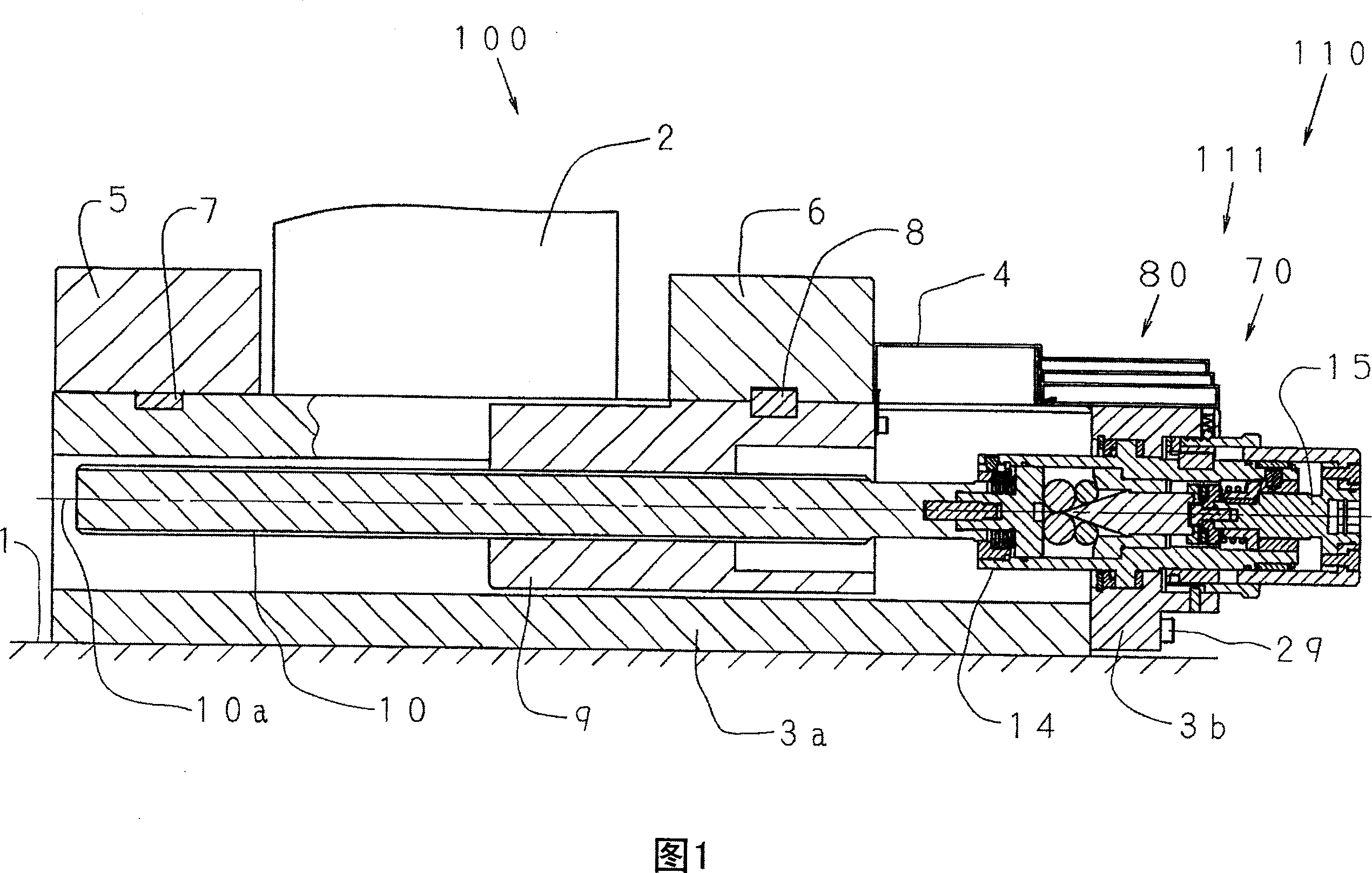
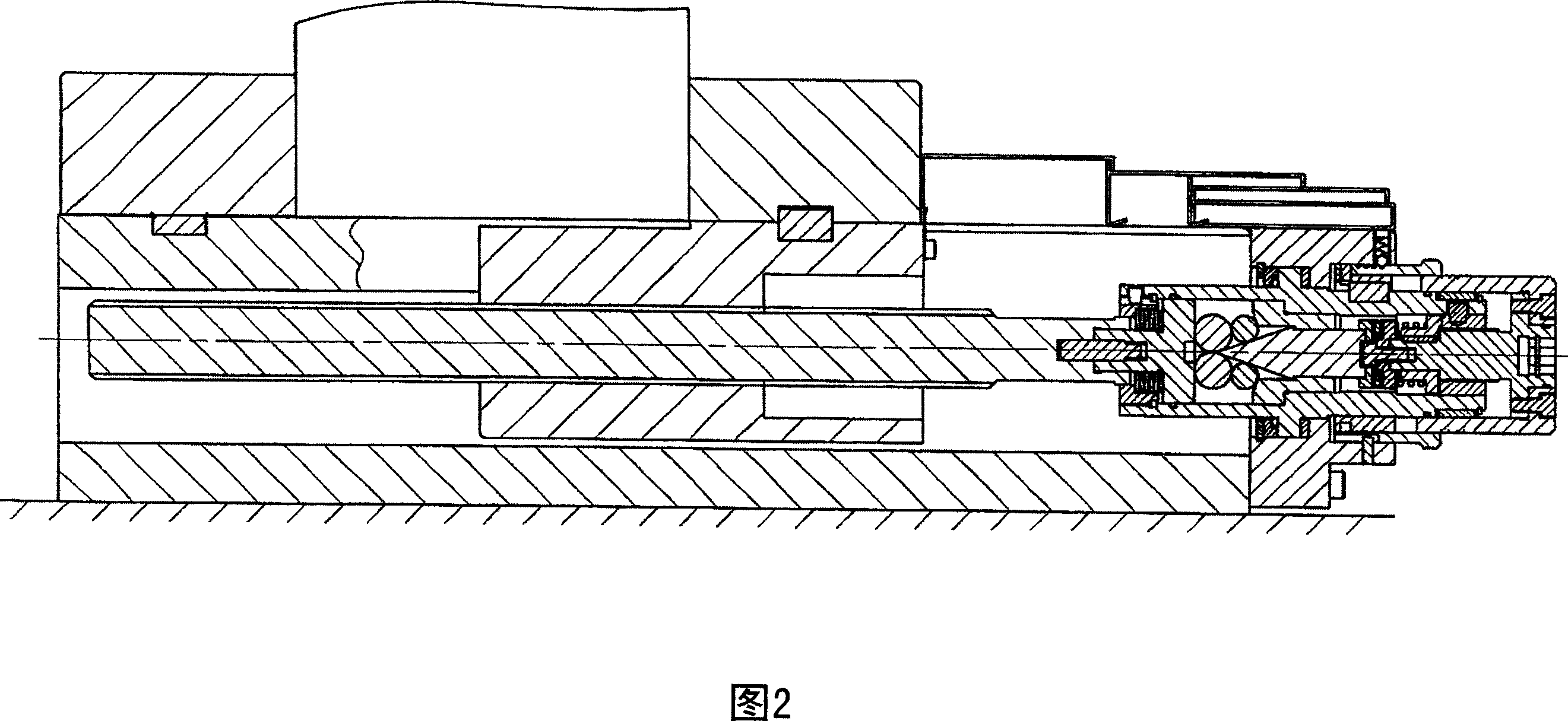
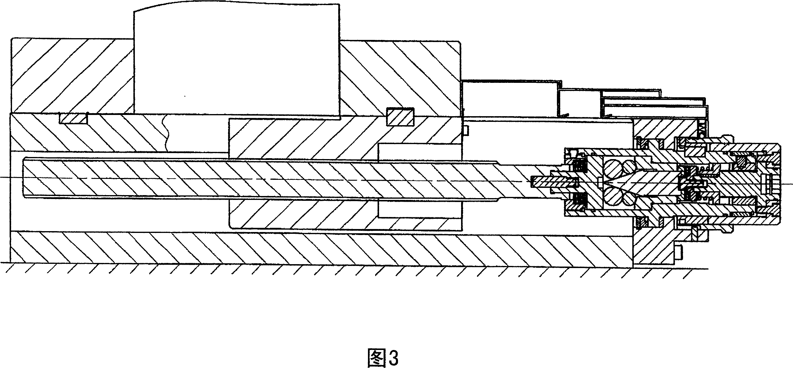
[0041] Hereinafter, embodiments of the present invention will be described with reference to the drawings. 1 to 7 show a vise 100 according to a first embodiment of the present invention. 1 to 3 are overall cross-sectional views of the vise 100, and FIG. 1 shows a state in which a workpiece is placed between the fixed jaw 5 and the movable jaw 6, and shows the state before the workpiece holding operation is started. 2 shows that the workpiece holding action is started, the rotation of the rotary propulsion shaft 15 is transmitted to the hollow shaft 14 through the clutch device 70 and the screw shaft 10 is rotated, and the workpiece 2 is clamped between the two jaws 5,6. FIG. 3 shows the state where the workpiece 2 is held with a predetermined clamping force after the rotation transmission of the clutch device 70 is released, and the rotary propulsion shaft 15 is further rotated. Fig. 4 is an enlarged view of main parts of Fig. 1 . FIG. 5 is an external view showing an inner...


PUM


Abstract

The invention relates to a plier with a reinforcement device and a clamping force adjusting device which reduce the impact force blocking a rotating propulsion shaft. The pliers has a lead screw spindle for coupling with a movable jaw; the reinforcement device at an end side of the lead screw spindle; the rotating propulsion shaft adjoined to the reinforcement device; a rotatable hollow spindle, which can not move in the axial direction, supported on the body frame, and one end of which can not relatively rotate but can relative movably assort with the lead screw spindle, and another end of which assorts with the screw thread of the rotating propulsion shaft and transfers rotation thereof by a clutch. The clamping force adjusting device of the pliers with a reinforcement device has: a protrusion projecting in the lead screw spindle direction and inserted with the hollow spindle, a blacking ring which can not rotate relative to the body frame when the rotation transmission of the clutch is released; and a rotating propulsion member of the protrusion which is fixed to the rotating propulsion shaft and projects to the lead screw spindle direction from the side thereof and can assort with the protrusion of the blocking ring.

Description

technical field [0001] The present invention relates to the technology of a vise with a booster device, in detail, it relates to a movable vise that is pressed by a screw shaft and is restricted from rotation by a main body frame and moves in the axial direction of the screw shaft by the rotation of the mating screw shaft. In the booster device of the jaw, the technology of adjusting the clamping force of the workpiece clamped by the fixed jaw and the movable jaw by adjusting the pressure of the booster device on the screw shaft. Background technique [0002] A vise equipped with a booster device can obtain firm workpiece clamping force. In the publication of Patent Document 1, a mechanical booster is provided on the vise. The booster is arranged on one end side of the screw shaft and is supported by the main body frame so that it can rotate but cannot move in the axial direction. The hollow shaft, that is, the hollow shaft that cannot rotate relatively but can move relativ...

Claims


Application Information

Patent Timeline
IPC IPC(8): B25B1/10B25B1/24B25B1/02F16H25/20
CPCB23Q3/06B25B1/02B25B1/10B25B1/2457
Inventor 多田裕之
Owner TSUDAKOMA KOGYO KK
Why Eureka
Eureka Blog
Learn More