Metal vapor discharge lamp and method of producing the same, and reflector-equipped lamp

A metal vapor, discharge lamp technology, applied in the manufacture of discharge tubes/lamps, parts of gas discharge lamps, discharge lamps, etc., can solve problems such as breakage, reduced operating efficiency, and the separation of the luminous tube 6, and achieves suppression of breakage, The effect of improving operational efficiency

Inactive Publication Date: 2006-11-08
PANASONIC CORP
View PDF1 Cites 0 Cited by
  • Summary
  • Abstract
  • Description
  • Claims
  • Application Information

AI Technical Summary

Problems solved by technology

But, except that the holding of the luminous tube 6 is in a very unstable state, the diameter of the external lead wire 13 is 0.5 mm to 0.9 mm, and the inner diameter of the exhaust pipe 12 inserted into it is 2.0 mm to 2.5 mm. The operation in the exhaust pipe 12 needs to be very cautious, and there is bound to be a problem of reducing the operating efficiency of this process
[0018] In addition, in the manufactured metal vapor discharge lamp, when an impact is applied from the outside during transportation, etc., the arc tube 6 is likely to be separated from a predetermined position inside the outer tube 5, and the outer tube 5 may come into contact with the arc tube 6 due to the impact. And the situation of their respective damage

Method used


Image

  • Metal vapor discharge lamp and method of producing the same, and reflector-equipped lamp
  • Metal vapor discharge lamp and method of producing the same, and reflector-equipped lamp
  • Metal vapor discharge lamp and method of producing the same, and reflector-equipped lamp

Examples


Embodiment Construction

[0076] Hereinafter, the best mode for carrying out the present invention will be described with reference to the drawings.

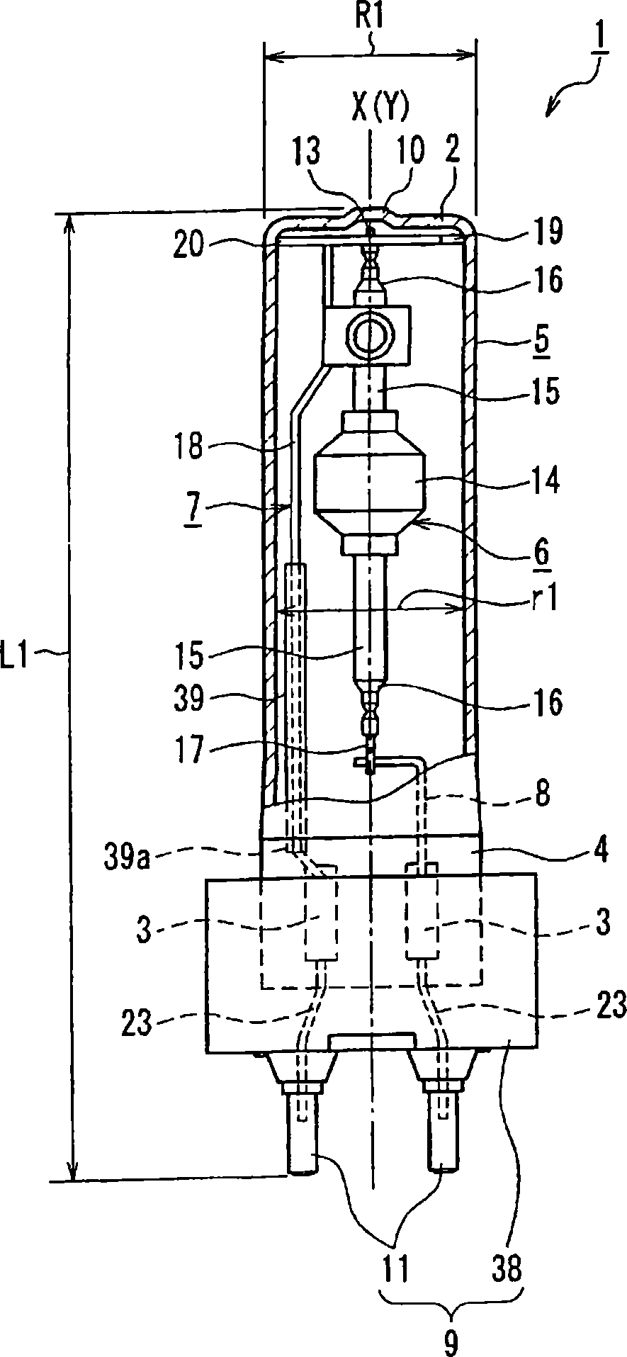
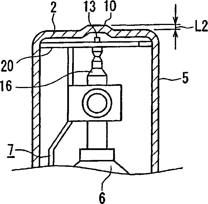
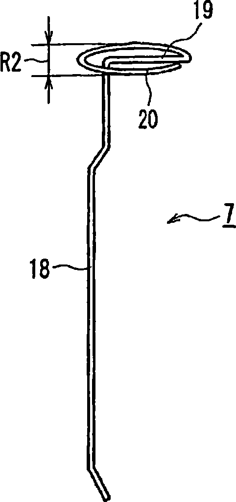
[0077] figure 1 A ceramic metal halide lamp 1 with a rated power of 70 W according to the first embodiment of the present invention is shown. This lamp has, for example, a substantially cylindrical outer tube 5 made of quartz glass, an arc tube 6 disposed inside the outer tube 5 , two power supply lines 7 and 8 supporting the arc tube 6 , and a lamp attached to the outer tube 5 . The lamp cap 9 at the end.

[0078] The overall length L of the outer tube 5 1 It is 100 mm, and has a closed portion 2 at one end, and a crush seal portion 4 in which two metal foils 3 are sealed at the other end. The full length L 1 It shows the distance from the front end of the detachment part 10 mentioned later to the front end of the terminal 11 of the base 9 mentioned later. Power supply lines 7 and 8 are provided for supplying external power to electrodes (not show...


PUM


Abstract

A lamp is provided with an outer tube (5) having a blocked section (2) at one end and a sealed section (4) at the other end with metal foils (3) sealed thereto, a light emitter (6) disposed in the outer tube (5), and power supply wires (7, 8) connected at one of their respective ends to the metal foils (3) and drawn at the other ends into the outer tube (5) and connected to outer lead wires (13, 17) led out from the light emitter (6). The light emitter (6) is supported by the power supply wires (7, 8). The power supply wire (7) has a holding section (contact section (20)) which holds the light emitter (6) at a predetermined position in the outer tube (5) in that at least part of the holding section contacts the inner surface of the outer tube (5). It is possible to stably hold the light emitter at a predetermined position in the outer tube to suppress breakage of the light emitter or outer tube due to shocks from outside and in the aspect of production it is possible to improve operating efficiency.

Description

technical field [0001] The present invention relates to a metal vapor discharge lamp having a structure in which a luminous tube is accommodated in an outer tube, a manufacturing method thereof, and a lamp with a reflector. Background technique [0002] Among conventional metal vapor discharge lamps, such as ceramic metal halide lamps, there are known lamps that are highly compact and used for shop lighting, etc. Figure 8 A lamp having a structure as shown. This lamp has a cylindrical quartz glass outer tube 33 , an arc tube 6 accommodated in the outer tube 33 , power supply lines 34 and 35 , and a cap 9 attached to an end of the outer tube 33 . [0003] The outer tube 33 has a tip-off portion 10 at one end and a sealing portion 4 in which the metal foil 3 is sealed at the other end. The arc tube 6 is accommodated in the outer tube 33 such that the central axis Y in the longitudinal direction substantially coincides with the central axis X in the longitudinal direction of ...

Claims


Application Information

Patent Timeline
IPC IPC(8): H01J61/34F21S8/10H01J5/54H01J9/24H01J9/32H01J9/36H01J61/36
CPCH01J9/36H01J5/54H01J61/34
Inventor 吉田雅人清水哲也柿坂俊介
Owner PANASONIC CORP
Why Eureka
Try Eureka