Feed grinding device

A grinding device and feed technology, applied in heating devices, dryers, grain processing, etc., can solve problems such as waste, and achieve the effect of facilitating subsequent processing and use

Inactive Publication Date: 2019-04-05
陆左琴
View PDF0 Cites 3 Cited by
  • Summary
  • Abstract
  • Description
  • Claims
  • Application Information

AI Technical Summary

Problems solved by technology

[0003] The purpose of the present invention is, aiming at the prior art, after the feed is mixed and dried, there will always be a small amount of feed that is bonded into large particles, and in order to avoid the waste of feed, it is generally necessary to dry the large particle feed Grinding, so as to facilitate its continued use, provide a feed grinding device

Method used


Image

  • Feed grinding device

Examples


Embodiment Construction

[0014] The present invention will be further described below in conjunction with specific embodiment:

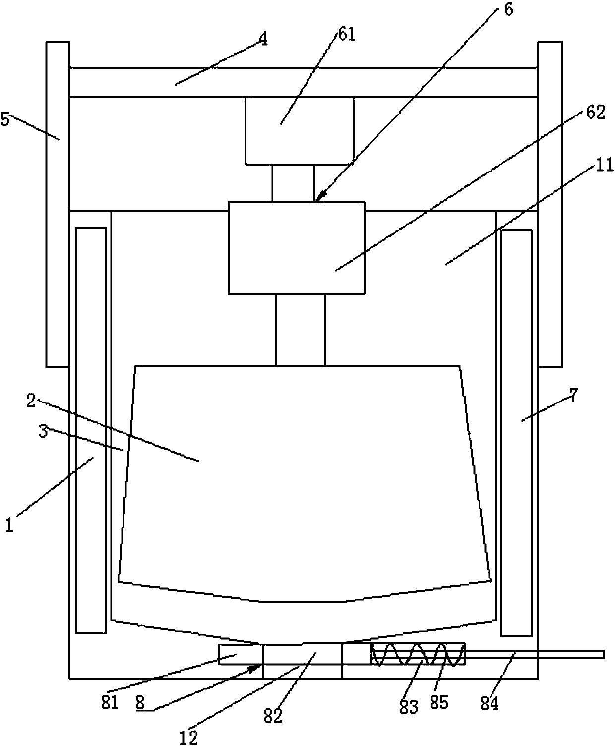
[0015] Such as figure 1 As shown, a feed grinding device includes a cylinder body 1, a grinding roller 2, a feed port 11, a discharge port 12, and a driving device 6. The grinding roller 2 is conically arranged, and the grinding roller 2 is arranged in the cylinder body 1. There is a gap 3 between the grinding roller 2 and the inner side wall of the cylinder 1, the gap 3 gradually narrows from the top to the bottom of the cylinder 1, there are struts 5 on both sides of the cylinder 1, and there is a gap between the two struts 5 Crossbeam 4, driving device 6 comprises driving motor 61 and electric cylinder 62, and the base of driving motor 61 is arranged on the crossbeam 4, and the output end of driving motor 61 is connected with the base of electric cylinder 62, and the output end of electric cylinder 62 is connected with grinding roller. The upper middle part of 2 is fixed...


PUM


Abstract

The invention provides a feed grinding device. The feed grinding device comprises a barrel body, a grinding roller, a charge hole, a discharge hole and a drive device, wherein the grinding roller is tapered; the grinding roller is arranged in the barrel body; a gap is formed between the grinding roller and the inner side wall of the barrel body; the gap is gradually reduced from the upper side ofthe barrel body to the lower side of the barrel body; supporting rods are arranged at the two sides of the barrel body; a beam is arranged between the two supporting rods; the drive device comprises adrive motor and an electric gas cylinder; the base of the drive motor is arranged on the beam; the output end of the drive motor is connected with the base of the electric gas cylinder; the output end of the electric gas cylinder is fixedly connected with the middle part above the grinding roller; the charge hole is formed in the upper portion of the barrel body; the discharge hole is formed in the lower portion of the barrel body; and the discharge hole is equipped with a sealing device. The feed grinding device realizes feeding of large-particle feed, and is convenient for follow-up processing use.

Description

technical field [0001] The invention relates to a feed grinding device. Background technique [0002] In large-scale breeding bases and feed production bases, feed mixers are used to mix various feed varieties together. The raw materials used include powder, liquid ingredients, and paste materials. If these three forms of materials are directly put into the production line, not only can they not be mixed evenly, which will affect the quality of the feed, but also these materials will adhere to the inner wall of the equipment. , or the pipes of the equipment will be blocked, or the sieve will be stuck, resulting in shutdown and production stoppage. Therefore, the general practice is to mix the powder, liquid ingredients, and paste materials evenly before the materials enter the production line. In order to ensure that the feed is fully mixed, it is necessary to ensure that the feed is dry. However, after the feed is mixed and dried, there will always be a small amount of fe...

Claims


Application Information

Patent Timeline
Patent Type & Authority Applications(China)
IPC IPC(8): B02C4/10B02C4/30B02C1/00B02C4/42F26B23/04
CPCB02C4/10B02C1/005B02C4/30B02C4/42F26B23/04
Inventor 陆左琴
Owner 陆左琴
Why Eureka
Try Eureka