Supercharge Your Innovation With Domain-Expert AI Agents!

Variable coupling rotation disc

A technology of turning the disc together, applied in the direction of large fixed members, metal processing machinery parts, metal processing equipment, etc., can solve problems affecting work efficiency, etc., and achieve the effect of easy maintenance, small size and simple assembly

Inactive Publication Date: 2019-04-05
SHENYANG ZHICHANG TECH CO LTD
View PDF0 Cites 0 Cited by
  • Summary
  • Abstract
  • Description
  • Claims
  • Application Information

AI Technical Summary

Problems solved by technology

[0002] When the rotating disk is rotating, it will generally drive the rotating table for positioning the rotating disk through the synchronous belt and gear chain transmission. Since the synchronous belt and gear chain transmission have certain errors, the error will be amplified during transmission, so Regular adjustments are required, affecting work efficiency

Method used


Image

  • Variable coupling rotation disc

Examples


Embodiment Construction

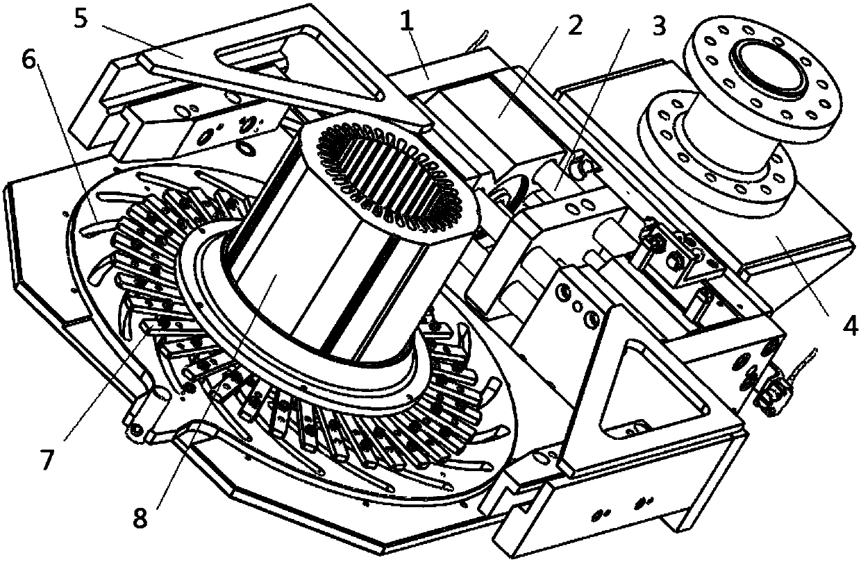
[0007] The present invention is described in detail below in conjunction with accompanying drawing, comprise frame 1, be provided with cylinder rod 3 on described frame 1, air pump push rod 2 and cylinder rod 3 are coaxially arranged together, on one side of frame, connect a Air pump 4 is provided with two brake chucks 5 on the other side of frame 1, is provided with rotating disk 6 at the thin-walled place of frame 1, is provided with rotary hinge 7 on rotating disk 6, and rotating disk 6 and The rotary hinges 7 are coaxially arranged together, and a fixture 8 is arranged at the center of the rotating disk 6 .


PUM


Abstract

The invention discloses a variable coupling rotation disc. The rotation disc comprises a rack, and through cooperation of rotating blades, rotating fan blades and groove holes, a subdivision precisiondisc with the locking function can be finished. The variable coupling rotation disc has the advantages that assembling is easy, rigid connection is adopted between the structures, the size is small,reliability is high, and maintaining is easy.

Description

technical field [0001] The invention relates to a mechanical processing device, in particular to a variable coupling rotating disc. Background technique [0002] When the rotating disk is rotating, it will generally drive the rotating table for positioning the rotating disk through the synchronous belt and gear chain transmission. Since the synchronous belt and gear chain transmission have certain errors, the error will be amplified during transmission, so Regular adjustments are required, affecting work efficiency. Contents of the invention [0003] The purpose of the present invention is to provide a variety of coupling rotating disk, the specific technical scheme is as follows: [0004] Including the frame, the frame is provided with a cylinder rod, the air pump push rod and the cylinder rod are coaxially arranged together, an air pump is fixedly connected to one side of the frame, and two brakes are provided on the other side of the frame The chuck is provided with a...

Claims


Application Information

Patent Timeline
IPC IPC(8): B23Q1/64
CPCB23Q1/64
Inventor 潘明霞
Owner SHENYANG ZHICHANG TECH CO LTD
Features
  • R&D
  • Intellectual Property
  • Life Sciences
  • Materials
  • Tech Scout
  • Unparalleled Data Quality
  • Higher Quality Content
  • 60% Fewer Hallucinations
Learn More