Al technical title is built by PatSnap Al team. It summarizes the technical point description of the patent document.
A technology of gravure printing machines and printing machines, which is applied in the direction of gravure rotary printing machines, printing machines, rotary printing machines, etc., which can solve problems such as damage and fracture, metal fatigue of scraping blades, and influence on scraping effect, so as to save costs and avoid Effects of blocked return pipes
Active Publication Date: 2020-12-15
广东法拉利彩印实业有限公司
View PDF15 Cites 3 Cited by
Summary
Abstract
Description
Claims
Application Information
AI Technical Summary
This helps you quickly interpret patents by identifying the three key elements:
Problems solved by technology
Method used
Benefits of technology
Problems solved by technology
[0005] In order to make up for the deficiencies of the existing technology, solve the problems that the long-term work of the printing machine will easily lead to metal fatigue of the squeegee and cause damage and fracture, and after the ink adheres to the bottom of the squeegee, the effect of squeegee will be easily affected if the time is too long ; The present invention proposes a gravure printing machine
Method used
Image
Click on the blue label to locate the original text in one second.
Reading with bidirectional positioning of images and text.
Examples
Embodiment approach
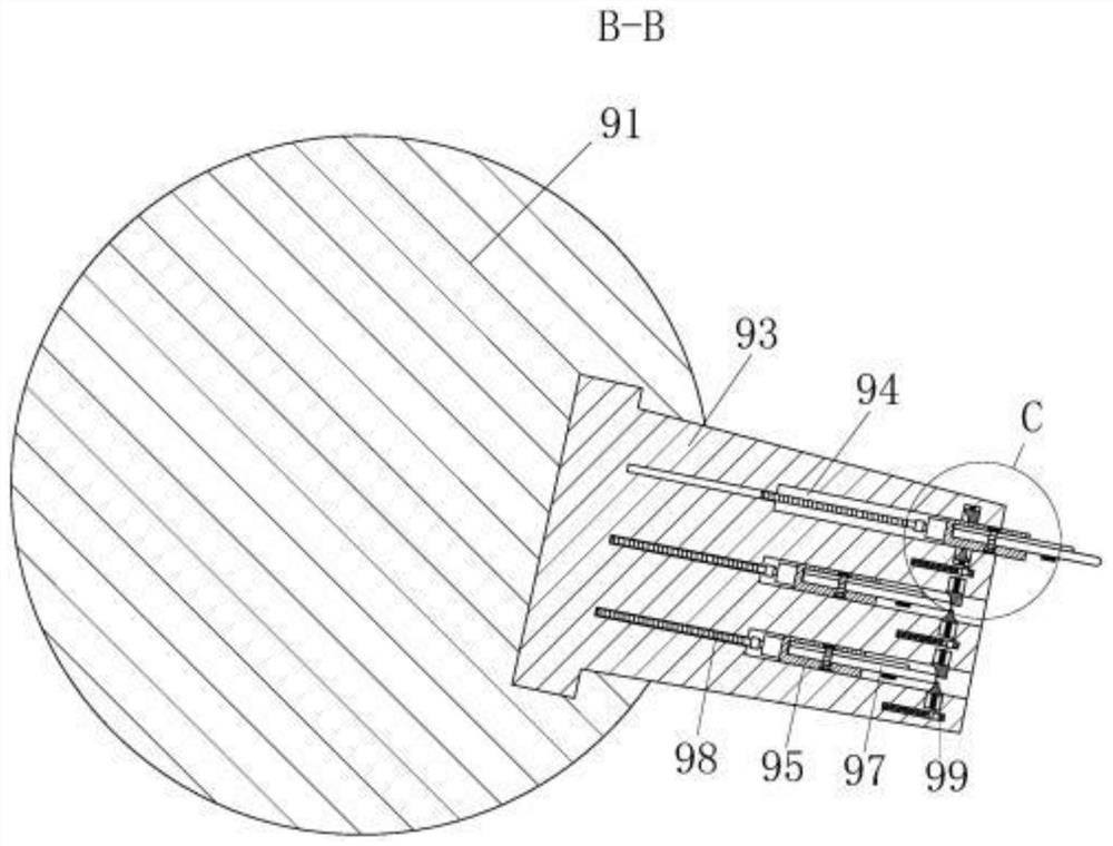
[0025] As an embodiment of the present invention, the grinding unit 99 includes a No. 1 whetstone 991, a No. 2 whetstone 992 and a No. 1 spring; the No. 1 whetstone 991 is slidably arranged in the No. 1 groove opened on the top wall of the installation groove 94 Inside, the No. 1 oil stone 991 is connected in the No. 1 groove through the No. 1 spring; the No. 2 oil stone 992 is slidably connected in the No. 2 groove opened on the bottom wall of the installation groove 94, and the No. 2 oil stone 992 is connected through the No. 2 spring. In the No. 2 groove, the left sides of the No. 2 oil stone 992 and the No. 1 oil stone 991 are arc-shaped, so that the ink scraper 97 can stretch out. When the No. 2 servo motor drives the ink scraper 97 to retract in the installation groove 94, the No. 1 oil stone 991 is pressed on the upper side of the ink scraper 97 under the promotion of the No. 1 spring, and the upper side of the ink scraper 97 is polished. No. 9 oil stone 992 is pressed ...
PUM
Abstract
The invention belongs to the technical field of printing equipment, and particularly relates to a gravure printing machine. The gravure printing machine comprises a shell, a power device, a controller, a feeding roller, a discharging roller, a guiding roller set, an ink tank, an ink roller, a plate cylinder, an impression cylinder and a squeegee mechanism. The power device is mounted at the rear side of the shell for the operation of the printing machine; the controller is used for controlling the operation of the printing machine; the feeding roller, the discharging roller, the guiding rollerset, the ink tank, the ink roller, the plate cylinder, and the impression cylinder are rotationally arranged on the shell; and the squeegee mechanism is arranged on the shell. According to the gravure printing machine, a printed material sequentially winds across the feeding roller, the guiding roller set, the impression cylinder and the discharging roller, through cooperation of a plurality of sets of screws, a second servo motor and a U-shaped clamp plate, the squeegee can be replaced without stopping the machine, the printing machine can work efficiently for a long time, and the squeegee will not damage or break after the printing machine work for a long time.
Description
technical field [0001] The invention belongs to the technical field of printing equipment, in particular to a gravure printing machine. Background technique [0002] Printing is a technology that transfers the ink to the surface of paper, fabric, plastic, leather and other materials through plate making, ink application, and pressurization to copy the contents of the original manuscript in batches. Printing is the process of transferring the approved printing plate to the substrate through printing machinery and special ink. [0003] A gravure printing machine is a machine that uses gravure plates for printing. The graphic part of the printing plate is concave, and the blank part is on the same plane as the outer circle of the printing plate cylinder. When the gravure printing machine is printing, the entire printing plate cylinder is inked, and the ink on the blank part of the printing plate is scraped off with a scraper , leave the ink in the graphic part, and then pass ...
Claims
Application Information
Patent Timeline
Application Date:The date an application was filed.
Publication Date:The date a patent or application was officially published.
First Publication Date:The earliest publication date of a patent with the same application number.
Issue Date:Publication date of the patent grant document.
PCT Entry Date:The Entry date of PCT National Phase.
Estimated Expiry Date:The statutory expiry date of a patent right according to the Patent Law, and it is the longest term of protection that the patent right can achieve without the termination of the patent right due to other reasons(Term extension factor has been taken into account ).
Invalid Date:Actual expiry date is based on effective date or publication date of legal transaction data of invalid patent.