

Adjustable dust suction blackboard eraser
A blackboard eraser, adjustable technology, applied in the field of blackboard eraser, to achieve the effects of easy collection, backflow prevention, and strong adjustability
- Summary
- Abstract
- Description
- Claims
- Application Information
AI Technical Summary
Problems solved by technology
Method used
Image

Examples
Embodiment Construction
[0017] The following will clearly and completely describe the technical solutions in the embodiments of the present invention with reference to the accompanying drawings in the embodiments of the present invention. Obviously, the described embodiments are only some, not all, embodiments of the present invention. Based on the embodiments of the present invention, all other embodiments obtained by persons of ordinary skill in the art without making creative efforts belong to the protection scope of the present invention.
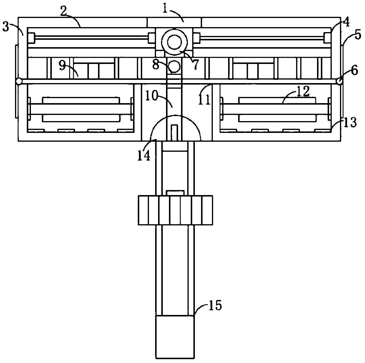
[0018] The present invention provides such figure 1 , figure 2 and image 3 The shown adjustable dust-absorbing blackboard eraser comprises a blackboard eraser main body 10, the two sides of the blackboard eraser main body 10 are provided with turning bearing shafts 6, and the two sides of the turning bearing shaft 6 are provided with splicing receiving surfaces 5, and the The upper surface of the splicing joint surface 5 is provided with a magnetic suction...
PUM
 Abstract
Description
Claims
Application Information