Electric vehicle frame structure being convenient to fold
A frame structure, electric vehicle technology, applied in the field of mechanical structure, can solve the problems of poor driving experience, large limitations, and large operating range of the shock absorption mechanism, and achieves improved shock absorption stability, high use stability, and good adjustment. sexual effect
- Summary
- Abstract
- Description
- Claims
- Application Information
AI Technical Summary
Problems solved by technology
Method used
Image
Examples
Embodiment 1
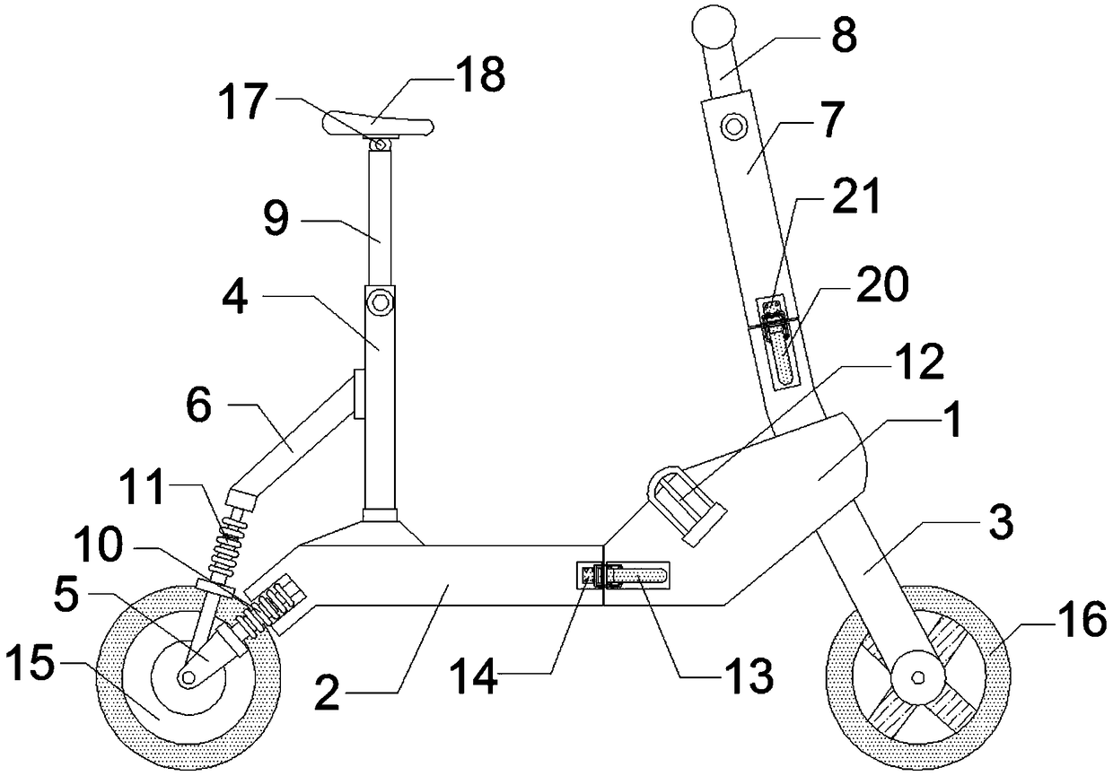
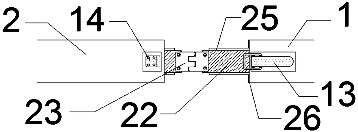
[0017] Such as Figure 1-5 As shown, an electric vehicle frame structure that is easy to fold includes a main frame 1, a load-bearing frame 2, a main rod 3, a seat post 4, and a drawing groove 27. One end of the main frame 1 is provided with a load-bearing frame 2, and the main frame 1. The other end is provided with a main rod 3 through a bearing, and the top of the main rod 3 is provided with a faucet frame 7, and the faucet frame 7 and the load-bearing frame 2 are both provided with a pull-out groove 27, and the inside of the pull-out groove 27 is set through a slideway 28 First drawing column 24, one end of the main frame 1 and main rod 3 is welded to the second drawing column 22 corresponding to the first drawing column 24, and the top of the first drawing column 24 and the second drawing column 22 and the bottom are provided with sliders 25 corresponding to slideways 28, hinges 23 are installed between the first pull column 24 and the second pull column 22, and the main ...
Embodiment 2
[0023] Such as Figure 1-5 As shown, an electric vehicle frame structure that is easy to fold includes a main frame 1, a load-bearing frame 2, a main rod 3, a seat post 4, and a drawing groove 27. One end of the main frame 1 is provided with a load-bearing frame 2, and the main frame 1. The other end is provided with a main rod 3 through a bearing, and the top of the main rod 3 is provided with a faucet frame 7, and the faucet frame 7 and the load-bearing frame 2 are both provided with a pull-out groove 27, and the inside of the pull-out groove 27 is set through a slideway 28 First drawing column 24, one end of the main frame 1 and main rod 3 is welded to the second drawing column 22 corresponding to the first drawing column 24, and the top of the first drawing column 24 and the second drawing column 22 and the bottom are provided with sliders 25 corresponding to slideways 28, hinges 23 are installed between the first pull column 24 and the second pull column 22, and the main ...
PUM
 Abstract
Description
Claims
Application Information
 - R&D
- Intellectual Property
- Life Sciences
- Materials
- Tech Scout
- Unparalleled Data Quality
- Higher Quality Content
- 60% Fewer Hallucinations
Browse by: Latest US Patents, China's latest patents, Technical Efficacy Thesaurus, Application Domain, Technology Topic, Popular Technical Reports.
© 2025 PatSnap. All rights reserved.Legal|Privacy policy|Modern Slavery Act Transparency Statement|Sitemap|About US| Contact US: help@patsnap.com


