Ball valve

A technology for ball valves and valve stems, which is applied to valve devices, cocks including cut-off devices, engine components, etc., and can solve problems such as easily damaged ball valves and leakage

Active Publication Date: 2019-04-05
派利阀门集团有限公司
View PDF6 Cites 0 Cited by
  • Summary
  • Abstract
  • Description
  • Claims
  • Application Information

AI Technical Summary

Problems solved by technology

[0004] In order to solve the problem that the sealing structure between the valve stem and the valve stem positioning hole in the existing ball valve is easily damaged and thus cause leakage of the ball valve, a sealing structure between the valve stem and the valve stem positioning hole is not easy to be damaged so as to reduce leakage Possibility of ball valve

Method used


Image

  • Ball valve
  • Ball valve
  • Ball valve

Examples


Embodiment 1

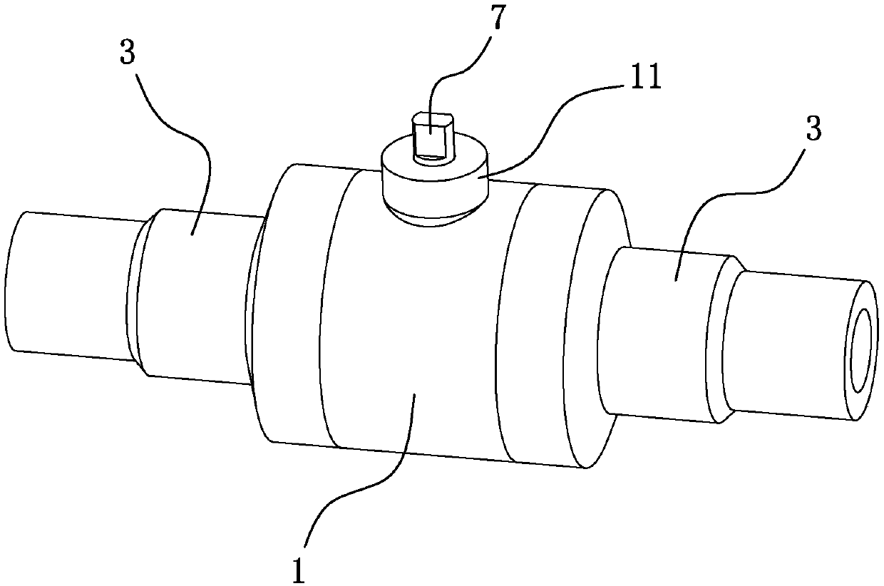
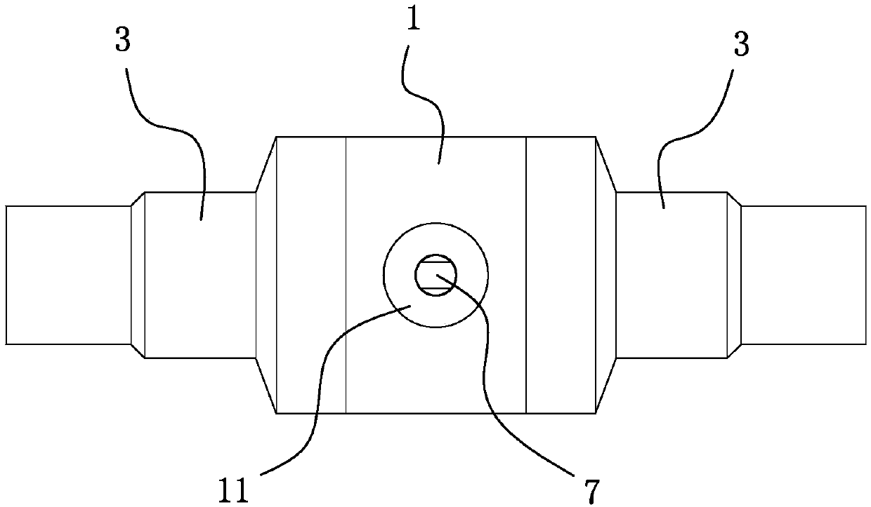
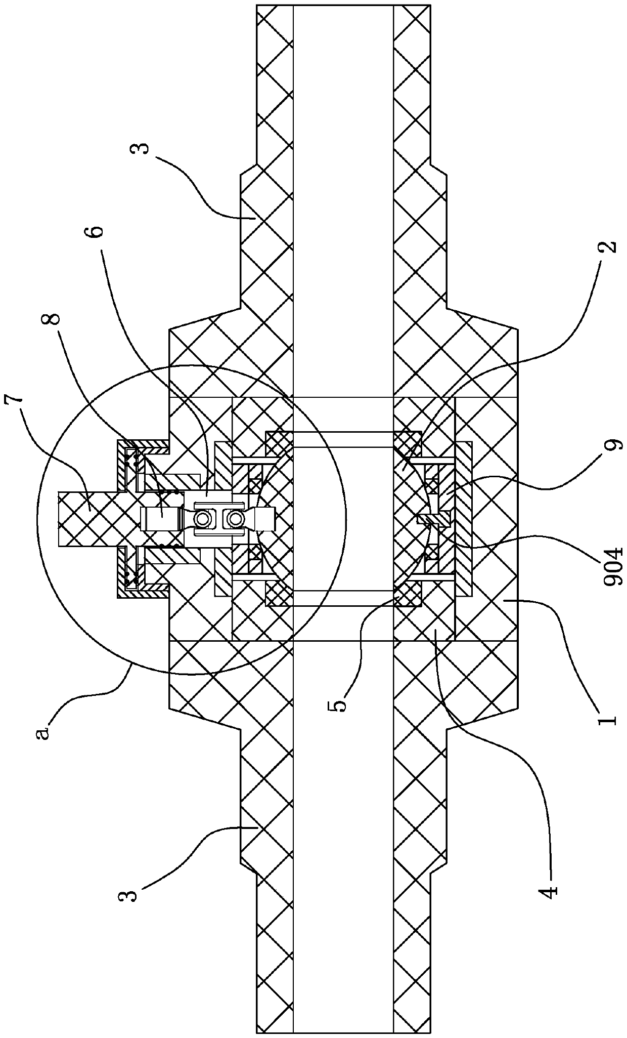
[0035] see Figure 1 to Figure 11 , a ball valve described in this embodiment at least includes a valve seat 1, a valve ball 2 disposed in the valve seat 1, and two connecting pipes 3 disposed on both sides of the valve seat 1, and each side of the valve ball 2 passes through a positioning Seat 4 is clamped and positioned, and the side facing the valve ball 2 of the two positioning seats 4 is provided with a first sealing ring 5 that fits and seals with the outer wall of the valve ball 2, and a valve stem is provided on the upper side of the valve seat 1 through the inner and outer walls Through hole 6.

[0036] The valve seat 1 is also provided with a valve stem 7 and a double-joint universal joint 8, the lower section of the valve stem 7 is located in the valve stem through hole 6, and the valve stem 7 and the valve stem through hole 6 are realized by a rotating sealing mechanism. Rotational sealing fit, the said rotating sealing mechanism is that the valve stem 7 is sleeve...

Embodiment 2

[0043] see Figure 12 to Figure 15 , this embodiment further makes the following improvements on the basis of embodiment one:

[0044] It also includes a valve stem locking mechanism 12. The valve stem locking mechanism 12 includes a positioning sleeve 1201 and a lifting ring 1202. The positioning sleeve 1201 is coaxially embedded in the valve stem through hole 6. The The valve stem 7 realizes rotation and sealing cooperation with the valve stem through hole 6 through the positioning sleeve 1201, and several O-rings 705 are set on the valve stem 7, and the O-rings 705 are in rotation and sealing cooperation with the inner wall of the positioning sleeve 1201; The positioning sleeve 1201 is provided with several slideways 1203 and several air pressure passages 1204. The slideways 1203 correspond to the air pressure passages 1204 one by one. The slideways 1203 are arranged vertically. The opening at the lower end communicates with one end of the corresponding air pressure channe...

Embodiment 3

[0047] see Figure 16 to Figure 17 , this embodiment further makes the following improvements on the basis of embodiment one:

[0048] It also includes a valve stem sealing mechanism 13, the valve stem sealing mechanism 13 includes a positioning sleeve 1201 and an inflatable sealing ring 1301, the positioning sleeve 1201 is coaxially embedded in the valve stem through hole 6, the valve The rod 7 realizes rotational sealing cooperation with the valve stem through hole 6 through the positioning sleeve 1201, and several O-rings 705 are set on the valve rod 7, and the O-rings 705 are rotationally and sealingly matched with the inner wall of the positioning sleeve 1201; The inner wall ring of the positioning sleeve 1201 is provided with a sealing ring limiting groove 1302, and the inflatable sealing ring 1301 is set in the sealing ring limiting groove 1302 and the ring is set on the outside of the valve stem 7; the positioning sleeve 1201 is provided with an inflation channel 1303 ...


PUM


Abstract

The invention discloses a ball valve, and relates to the technical field of ball valves for natural gas. The ball valve at least comprises a valve seat, a valve ball arranged in the valve seat and twoconnecting pipes arranged on the two sides of the valve seat, the two sides of the valve ball are each clamped and positioned through one positioning seat, the sides, facing the valve ball, of the two positioning seats are each provided with a first sealing ring attached to the outer wall of the valve ball, a valve rod through hole is formed in the upper side of the valve seat in a manner of penetrating through the inner and outer walls, and the valve seat is further provided with a valve rod and a double-joint cardan joint. The ball valve solves the problem that in an existing ball valve, asealing structure between a valve rod and a valve rod positioning hole is prone to being broken and consequently ball valve leakage is caused; and the ball valve is provided, a sealing structure between the valve rod and a valve rod positioning hole is not prone to being broken, and the possibility of leakage is reduced.

Description

technical field [0001] The invention relates to the technical field of ball valves, in particular to a ball valve for natural gas. Background technique [0002] Compared with ball valves for water, ball valves for natural gas have higher requirements for sealing. If leakage occurs during use, it will cause greater harm. [0003] In the existing ball valve structure, the valve stem is positioned on the valve seat and can only rotate in the positioning hole, while the valve ball is floating. When the ball valve in use is closed, the air pressure on one side of the valve ball will be greater than the air pressure on the other side, and the valve ball will deviate to the side where the air pressure is smaller, and the valve stem will not adapt to the deviation of the valve ball, and then The end connecting the valve stem and the valve ball is subjected to a transverse shear stress. This shear stress easily destroys the sealing structure between the valve stem and the valve ste...

Claims


Application Information

Patent Timeline
Patent Type & Authority Applications(China)
IPC IPC(8): F16K5/08F16K5/06
CPCF16K5/061F16K5/0689F16K5/08
Inventor 宣琦
Owner 派利阀门集团有限公司
Why Eureka
Try Eureka