
A hydraulic testing machine for engine assembly testing and its application method

A hydraulic testing machine and assembly detection technology, which is applied in the direction of measuring the increase and decrease rate of the fluid, using liquid/vacuum degree to measure the liquid tightness, etc., can solve the problem that the amount of cooling water and air cannot be absolutely controlled, and cannot be found in advance stably Problems such as the sealing of the cooling system, inconsistent changes in air density and water density, etc., to achieve true and reliable test data, to meet the sealing test of a wide range of models, and to stabilize the temperature field.

Active Publication Date: 2020-10-20
CHINA NORTH ENGINE INST TIANJIN
View PDF11 Cites 0 Cited by
  • Summary
  • Abstract
  • Description
  • Claims
  • Application Information

AI Technical Summary

Problems solved by technology

Because this method uses two media, air and water, the air density and water density change are inconsistent under the temperature change, and the amount of cooling water and air injected each time cannot be absolutely controlled, thus introducing two disadvantages of the water injection pressurization method When the test time is short, it is not sensitive to micro-leakage parts. When the test time is long, the different air pressure rise and fall factors introduced by the change of air density are included in the test pressure, so the product quality control is not strict.
And some special seals also need to check the temperature adaptability, and the water injection and pressurization method cannot heat the coolant in the cooling system
At the same time, due to the subjective factors of personnel introduced by the water injection pressurization method, effective process control cannot be carried out.
After the test, the sealing problem of the cooling system cannot be found in advance in a stable manner. In some newly developed models, failures caused by leakage often occur, thus increasing the cost of trial production after repeated installation and testing

Method used


Image

  • A hydraulic testing machine for engine assembly testing and its application method
  • A hydraulic testing machine for engine assembly testing and its application method

Examples


Embodiment Construction

[0049] It should be noted that, in the case of no conflict, the embodiments of the present invention and the features in the embodiments can be combined with each other.

[0050] In describing the present invention, it should be understood that the terms "center", "longitudinal", "transverse", "upper", "lower", "front", "rear", "left", "right", " The orientations or positional relationships indicated by "vertical", "horizontal", "top", "bottom", "inner" and "outer" are based on the orientations or positional relationships shown in the drawings, and are only for the convenience of describing the present invention and Simplified descriptions, rather than indicating or implying that the device or element referred to must have a particular orientation, be constructed and operate in a particular orientation, and thus should not be construed as limiting the invention. In addition, the terms "first", "second", etc. are used for descriptive purposes only, and should not be understood ...


PUM


Abstract

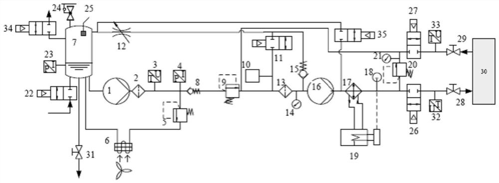
The invention provides a hydrostatic testing machine for engine assembly detection and an application method. The testing machine comprises a water tank, wherein the water tank is connected with a liquid supplementing circulation circuit, an exhaust circuit, a supplementary step-down circuit, a cooling liquid collection circuit, and a hydraulic pressure test circuit; the water tank is sequentiallyconnected with a first heat pump, a first water filter, a temperature transmitter, a first pressure transmitter, a first pressure regulating valve and an air cooling radiator to form the liquid supplementing circulation circuit; and a second water filter is sequentially connected with a first pressure gauge, a second heat pump, a heat exchanger, a temperature sensor, a third electromagnetic valve, a second temperature transmitter, a first manual ball valve, an engine / engine component, a second manual ball valve, a third temperature transmitter and a fourth electromagnetic valve to form the hydraulic pressure test circuit. The invention provides a set of reliable detection means for the quality control of the sealing performance of engine products, so that any cooling waterway sealing performance detection including the engine and the engine component can be realized, and the detection structure is high in accuracy and short in test time.

Description

technical field [0001] The invention belongs to the technical field of engine assembly, and in particular relates to a hydraulic testing machine for engine assembly detection and an application method. Background technique [0002] Engine sealing inspection is an important quality control process for the factory inspection after the engine assembly assembly. The purpose is to check the sealing performance of the engine cooling system to ensure that there will be no mutual intrusion between the cooling system and the lubrication system, and the cooling and fuel systems during engine operation. Guarantee the factory quality of the engine. However, some core components in the engine system, such as fuel injectors, cylinder liners, and cooling water pumps, are isolated from the engine cooling system by sealing rubber rings. When the process is not completely stable at the initial stage of design, due to changes in component assembly, material properties, or tolerances, parts ins...

Claims


Application Information

Patent Timeline
Patent Type & Authority Patents(China)
IPC IPC(8): G01M3/26
CPCG01M3/26
Inventor 刘峰春陈彪吴志强梁栋王宇王涛刘新华
Owner CHINA NORTH ENGINE INST TIANJIN
Learn More