
Industrial robot built-in wire harness wear and accelerated wear test method and device

A technology of industrial robots and testing methods, which is applied in the direction of measuring devices, testing wear resistance, instruments, etc., can solve problems such as not considering wiring harnesses, being unable to achieve integration, intelligence, integration, and ignoring the complex wear and tear of wiring harnesses

Active Publication Date: 2021-01-19
HANGZHOU DIANZI UNIV
View PDF9 Cites 0 Cited by
  • Summary
  • Abstract
  • Description
  • Claims
  • Application Information

AI Technical Summary

Problems solved by technology

First of all, the test device of the invention is too large and can only measure a specific type of wire harness within a specific length range for the tested wire harness, without considering the influence of the length of the wire harness on the wear test; secondly, the test method mainly relies on the upper and lower horizontal guide rails The regular simple reciprocating test does not carry out the wear test of the wire harness for the special working environment of the wire harness installed by the built-in wire harness type industrial robot. It is just a general wear test of the wire harness, ignoring the built-in wire harness The complex wear and tear of the wire harness in the joints of industrial robots; the mechanical arms at the joint head end and joint tail end of some industrial robots will form an angle constraint in actual work, and the wire harness will be constantly in this position during the working motion of the industrial robot. Friction in a structure constrained by angles, this friction and wear process is different from plane friction and wear
Then the test method adopts power-on test and X-ray scanning test method, which needs to take the wire harness out of the test device, and cannot achieve better integration, intelligence and integration.

Method used


Image

  • Industrial robot built-in wire harness wear and accelerated wear test method and device
  • Industrial robot built-in wire harness wear and accelerated wear test method and device
  • Industrial robot built-in wire harness wear and accelerated wear test method and device

Examples


Embodiment Construction

[0032] The present invention will be further described below in conjunction with the accompanying drawings.

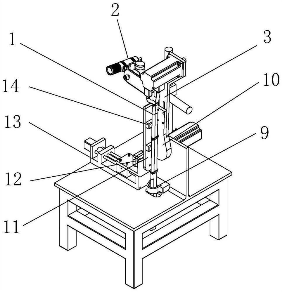
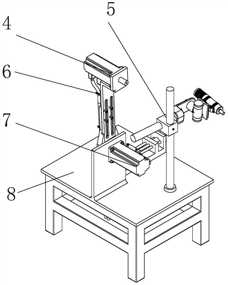
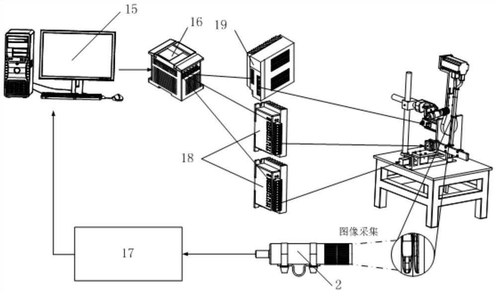
[0033] Such as figure 1 , 2 As shown in and 3, the built-in wire harness wear and accelerated wear test device for industrial robots mainly consists of multi-wire harness 1, camera 2, simulated mechanical arm 3, wire harness joint motor 4, camera spatial position adjustment device 5, multi-wire harness binding device 6, swing Motor 7, mounting base 8, hoop 9, swing arm 10, analog board 11, analog board swing and rotation device 12, analog board mobile platform 13, industrial computer 15, motor motion controller 16, swing motor driver 19, stepper motor The driver 18 and the image acquisition card 17 are composed.

[0034] The swinging and rotating device 12 of the simulation board comprises a swing angle motor and a connecting plate; the output shaft of the swing angle motor is fixed with the bottom end of the simulation board 11, and if the inside of the mechanical a...


PUM


Abstract

The invention discloses an industrial robot built-in wiring harness abrasion and accelerated abrasion test method and device. No method and no device specially aiming at the abrasion test of a built-in wiring harness of an industrial robot exist in the prior art. The device provided by the invention mainly consists of a plurality of wiring harnesses, a camera, a simulated mechanical arm, a wiringharness joint motor, a camera space position regulating device, a multi-wiring-harness bundling device, a swinging motor, an installing seat, a holding hoop, a swinging arm, a simulation board, a simulation board swinging rotation device, a simulation board moving platform, an industrial personnel computer, a motor movement controller, a swinging motor driver, a step motor driver and an image collection card. The plane abrasion test or joint constraint abrasion test can be selected; the swinging amplitude and the swinging period of the swinging motor are controlled according to the wiring harness abrasion mode or the wiring harness accelerated abrasion mode; next, an imaging recognition technology is used for recognizing the wiring harness abrasion region due to simulation; the wiring harness abrasion and accelerated abrasion detection intelligence is realized; and the image processing process is simple and efficient.

Description

technical field [0001] The invention belongs to the technical field of wear testing of industrial robots, and in particular relates to a method and device for testing reliability of built-in wire harness wear and accelerated wear of industrial robots. Background technique [0002] Industrial robots are one of the major symbols of contemporary industrial automation, and they replace a large number of dangerous or safety hazard jobs. Industrial robots are widely used in various industries. For industrial robots with built-in wire harness, the wear and tear of the built-in wire harness is inevitable, and the wear of the wire harness is one of the main reasons for the failure of this type of industrial robot. Therefore, it is very necessary to carry out the research and invention of the built-in wire harness wear test method and device of the industrial robot. [0003] At present, there are only a very small number of industrial robot built-in wire harness wear and accelerated...

Claims


Application Information

Patent Timeline
Patent Type & Authority Patents(China)
IPC IPC(8): G01N3/56G01N3/06
CPCG01N3/068G01N3/56G01N2203/0647G01N2203/0682
Inventor 倪敬任旭蒙臻
Owner HANGZHOU DIANZI UNIV
Learn More