
Light Ka-band reflecting-surface antenna and manufacturing method thereof

A reflective surface, lightweight technology, applied to antennas, electrical components and other directions, can solve the problems of complex welding process of panel adjustment support, difficult to achieve accuracy, easy to produce deformation, etc., to improve surface accuracy and adjustment efficiency, simplify Good design and shape retention

Pending Publication Date: 2019-04-05
NO 54 INST OF CHINA ELECTRONICS SCI & TECH GRP
View PDF0 Cites 5 Cited by
  • Summary
  • Abstract
  • Description
  • Claims
  • Application Information

AI Technical Summary

Problems solved by technology

[0005] 1. The weight of the antenna system is significantly increased, and the stiffness is poor;
[0006] 2. The welding process of the panel adjustment support is complicated, which may easily cause welding deformation;
[0007] 3. Aluminum alloy plates and Z-shaped ribs have poor moldability during the riveting process, are prone to deformation, and are difficult to achieve the precision after forming

Method used


Image

  • Light Ka-band reflecting-surface antenna and manufacturing method thereof
  • Light Ka-band reflecting-surface antenna and manufacturing method thereof
  • Light Ka-band reflecting-surface antenna and manufacturing method thereof

Examples


Embodiment Construction

[0055] The present invention will be further described in detail below in conjunction with the accompanying drawings and specific embodiments.

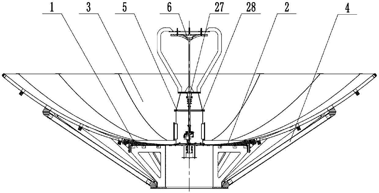
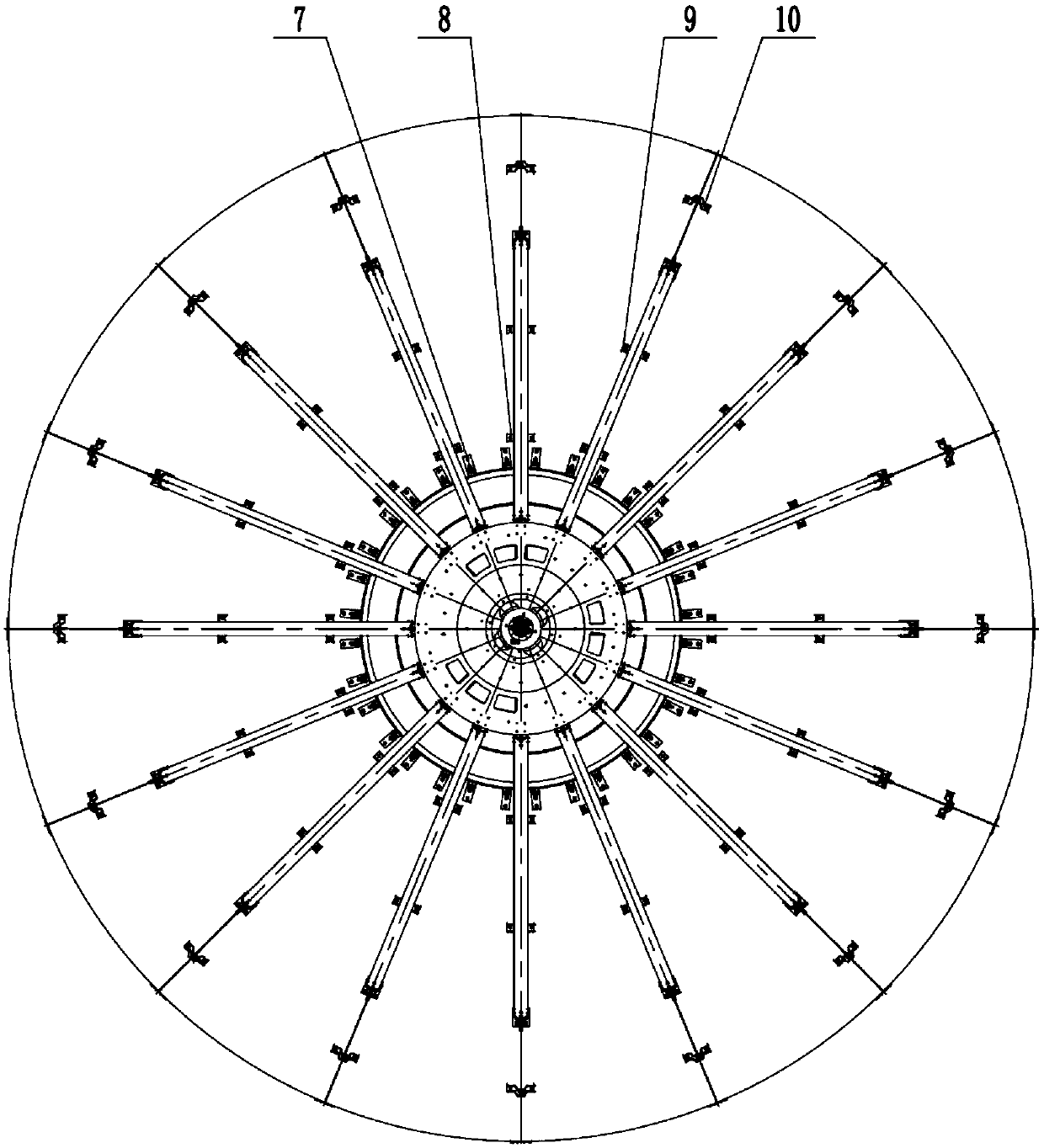
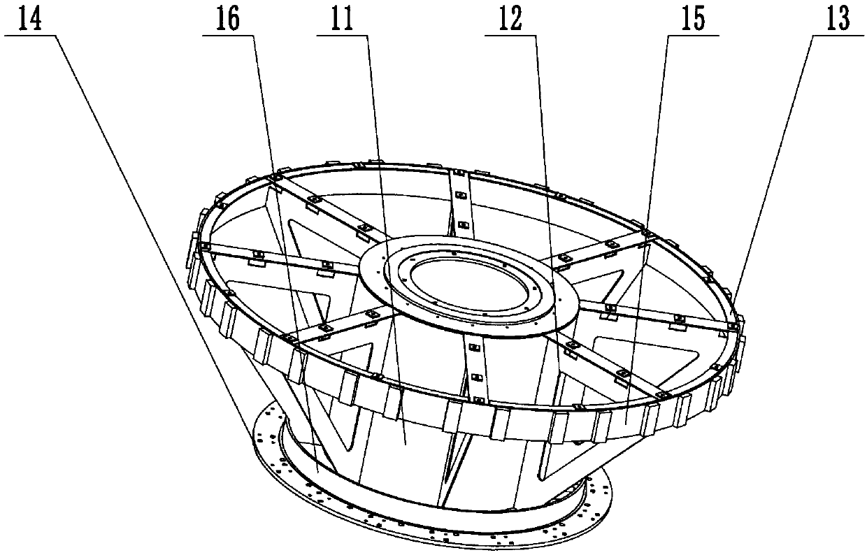
[0056] Such as Figure 1-12 As shown, a light-weight Ka-band reflector antenna includes a truss support 1, a central reflector 2, a main reflector unit 3, a rod assembly 4, a feed network support device 5, a secondary reflector 6, and multiple panel adjustments Assemblies 7-10, wherein, the feed source network supporting device 5 is provided with a feed source sleeve 28, and the feed source sleeve 28 is provided with a feed source network 27. The structure of each main reflector unit 3 is the same. The main reflector unit 3 includes an aluminum honeycomb body, a skin 17 arranged on the front and back sides of the aluminum honeycomb body, and six pairs of embedded parts 18-23 embedded in the aluminum honeycomb body. . For each main reflector unit 3, the first pair of embedded parts are two bottom embedded parts 18, which are respecti...


PUM


Abstract

The invention discloses a light Ka-band reflecting-surface antenna and a manufacturing method thereof, and relates to the technical field of reflecting-surface antennas. The antenna comprises a trusssupport, a central reflecting surface, a main reflecting surface, a feeding source network support device, a feeding source network and an auxiliary reflecting body, wherein each main reflecting-surface surface unit comprises a honeycomb main body, a skin and six pairs of pre-buried pieces, adjacent two main reflecting surface units are connected by a top connection piece and a panel adjustment assembly, and the main reflecting surface and the truss support are connected by a root adjustment assembly and a pull rod assembly. Each main reflecting surface unit is independently connected with thetruss support, and radial, circumferential and normal adjustment of the gesture of the main reflecting surface is achieved by the semi-enclosed panel adjustment assembly; the reflecting surfaces areintegrally connected by the panel adjustment assembly and are directly connected with a panel pre-buried piece, and the welding matching process is omitted; and by the open truss support and the pullrod assembly, the design of an antenna back rack is greatly simplified. The antenna has the characteristics of light weight, good shape maintenance, high adjustment efficiency and the like.

Description

technical field [0001] The invention belongs to the technical field of reflector antennas, in particular to a light-weight Ka-band reflector antenna and a manufacturing method thereof, which are suitable for the design and manufacture of circularly symmetrical reflector antennas with small and medium diameters, high precision, and operating frequencies above the Ka-band technology. Background technique [0002] With the rapid development of communication measurement and control and deep space detection technology, antennas have played an irreplaceable important role. Related technologies have higher and higher requirements for antenna operating frequency, surface accuracy, and light weight. Under the premise of satisfying the surface accuracy of the reflective panel, how to realize the lightweight of the antenna system is an important problem that needs to be faced in the project. [0003] At present, the traditional reflector antenna generally adopts the following structur...

Claims


Application Information

Patent Timeline
Patent Type & Authority Applications(China)
IPC IPC(8): H01Q19/19H01Q15/16H01Q15/14
CPCH01Q15/144H01Q15/165H01Q19/193
Inventor 刘健泉韩贵梅周书中郭向峰薛举段艳宾李增科梁成壮马颖川
Owner NO 54 INST OF CHINA ELECTRONICS SCI & TECH GRP
Learn More