Disposable test tube membrane structure

A membrane structure and test tube technology, applied in the direction of test tube holders/clamps, etc., can solve the problem that the test tube holder is easily contaminated, and achieve the effects of reducing the probability of cross-contamination, simple structure, and strong adaptability

Active Publication Date: 2019-04-09
杨柳
View PDF5 Cites 0 Cited by
  • Summary
  • Abstract
  • Description
  • Claims
  • Application Information

AI Technical Summary

Problems solved by technology

[0007] The main purpose of the present invention is to solve the problem that the test tube holder in the prior art is easily polluted, and to provide a disposable test tube membrane structure, which can keep the test tube rack clean and can be conveniently used in Among the existing thermostatic test tube racks, the structure is simple and can effectively reduce the probability of cross-contamination

Method used


Image

  • Disposable test tube membrane structure
  • Disposable test tube membrane structure
  • Disposable test tube membrane structure

Examples


Embodiment

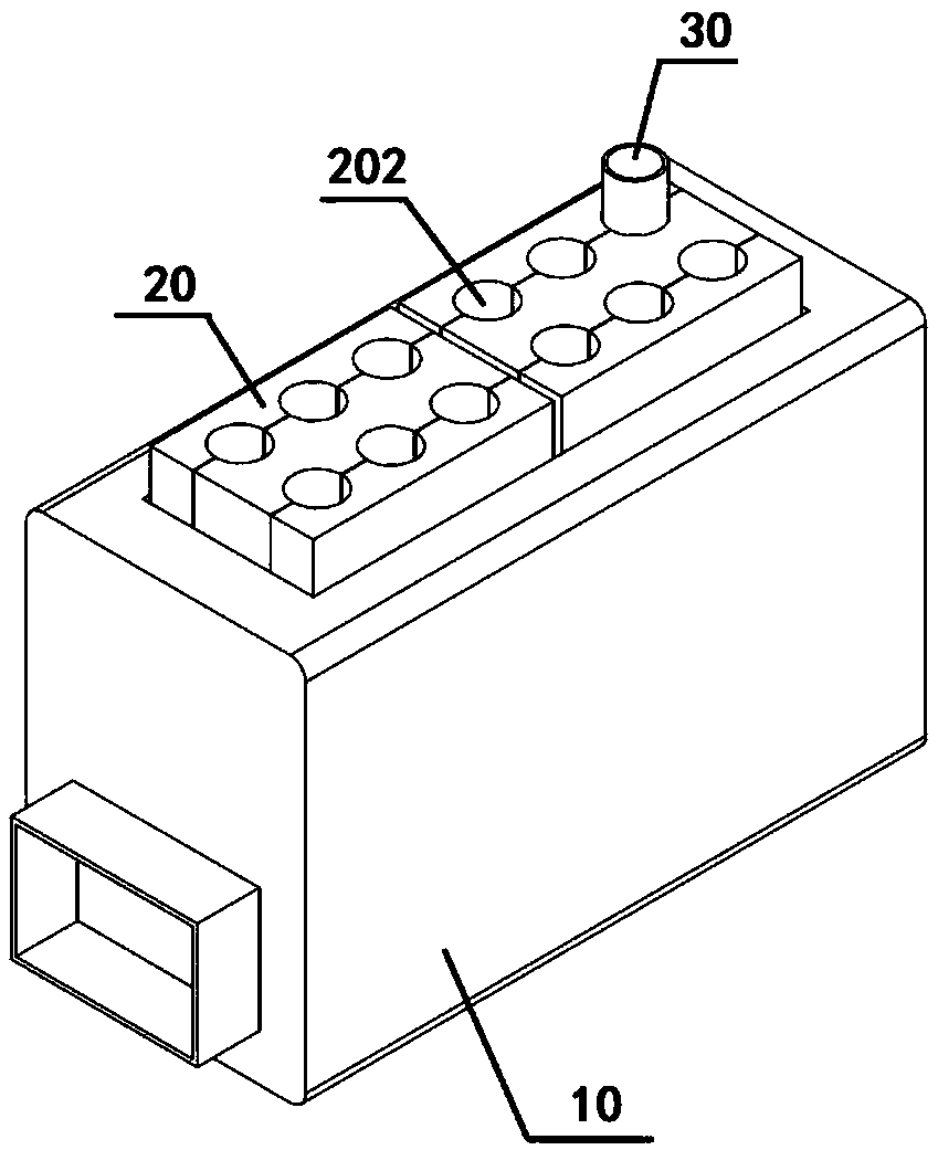
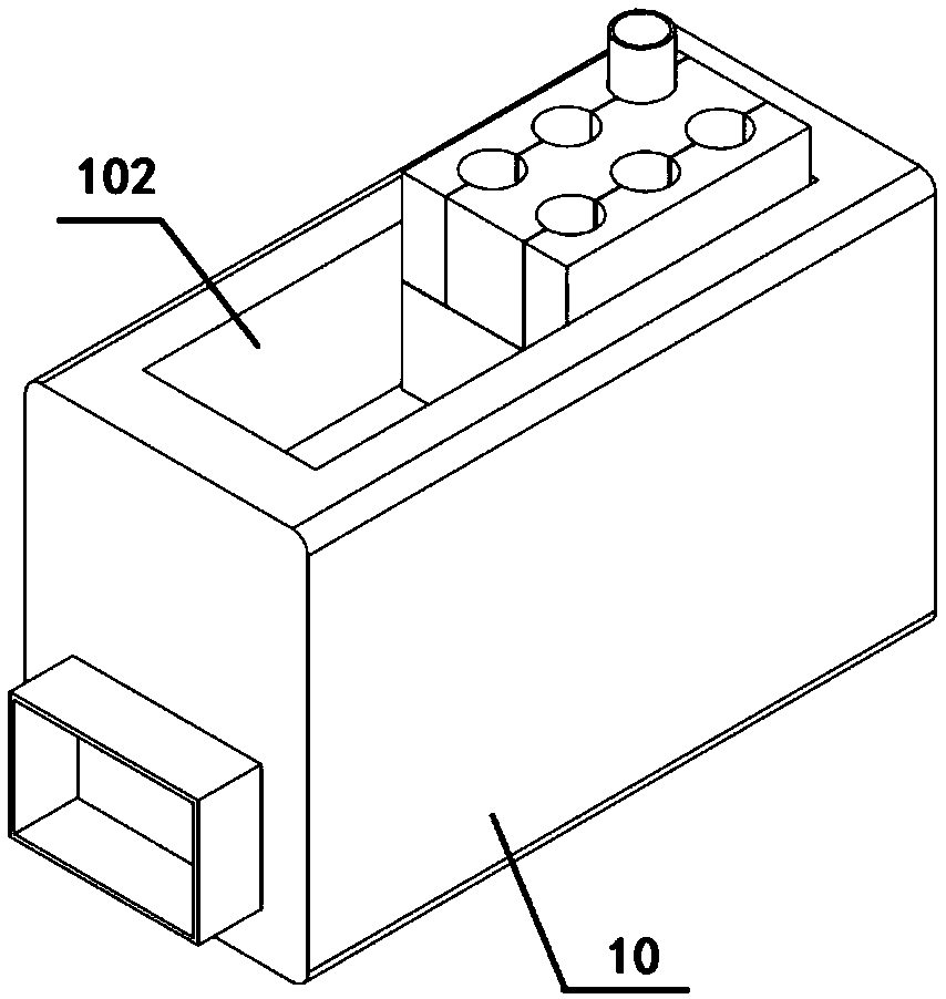
[0041] This embodiment provides a test tube membrane structure. The test tube membrane structure is used as Figure 1-2 The thermostatted test tube rack shown. The structure of the thermostatic test tube rack is as follows: Figure 1-2 As shown, it includes: a test tube rack base 10 , and a test tube holder 20 disposed on the test tube rack base 10 , and a number of test tube slots 202 are arranged on the test tube holder 20 .

[0042] During egg collection, the test tube 30 is inserted into the test tube slot 202 . When the liquid in the test tube 30 overflows or the liquid that changes the tube causes to splash, the liquid is easily spilled on the outer wall of the test tube 30, and when the test tube 30 is inserted into the test tube groove 202, the test tube groove 202 will be polluted; in addition, the splashed liquid It is also easy to infiltrate into the gap between the test tube holders 20 and the gap between the test tube holder 20 and the test tube rack base 10 .

...


PUM


Abstract

The invention relates to a test tube membrane structure, belongs to the field of medical equipment and specifically relates to a disposable test tube membrane structure. The disposable test tube membrane structure comprises a supporting body membrane sleeve and a pipe body membrane sleeve; the supporting body membrane sleeve is used for covering a test tube slot arranged on a test tube supportingbody; and the supporting body membrane sleeve is arranged to be opposite to the test tube slot and is capable of generating deformation towards the inside of the slot with the insertion of a test tubeso as to sleeve the outer surface of the test tube. The test tube membrane structure is capable of keeping a test tube rack clean, convenient to use in an existing constant-temperature test tube rack, simple in structure and capable of effectively reducing the probability of cross pollution.

Description

technical field [0001] The invention relates to a test tube membrane structure, which belongs to the field of medical equipment, in particular to a disposable test tube membrane structure. Background technique [0002] Existing thermostatic test tube racks do not have isolation membranes, and frequent tube changing activities cannot ensure that no follicle fluid is spilled on the outer wall of the test tube and pollutes the test tube holder during ovum collection. When the next patient collects eggs, the remaining follicular fluid in the unsterilized test tube rack contaminates the outer wall of the test tube of another patient, increasing the probability of mutual infection. [0003] Such as Figure 1-2 shown. A test tube holder 20 is arranged in the test tube rack base 10 , and several test tube grooves 202 are arranged on the test tube holder 20 . In the ovum collection technique, when the liquid in the test tube 30 overflows or the liquid splashes when changing the tub...

Claims


Application Information

Patent Timeline
Patent Type & Authority Applications(China)
IPC IPC(8): B01L9/06
CPCB01L9/06
Inventor 杨柳
Owner 杨柳
Why Eureka
Try Eureka