Plate deviation correction device and deviation correction method

A deviation correction device and plate technology, applied in the direction of transportation and packaging, conveyor objects, etc., can solve problems such as unfavorable processing, plate tilting, uneven machine connection, etc., to achieve the effects of reducing impact, enhancing load capacity, and reducing damage

Pending Publication Date: 2019-04-09
KEDA INDUSTRIAL GROUP CO LTD
View PDF1 Cites 4 Cited by
  • Summary
  • Abstract
  • Description
  • Claims
  • Application Information

AI Technical Summary

Problems solved by technology

[0002] During the processing and manufacturing of plates such as ceramics, glass, marble, etc., due to factors such as uneven connections between machines or improper steering, the plates are tilted, and the tilted plates will not be conducive to subsequent processing.

Method used


Image

  • Plate deviation correction device and deviation correction method
  • Plate deviation correction device and deviation correction method
  • Plate deviation correction device and deviation correction method

Examples


Embodiment 1

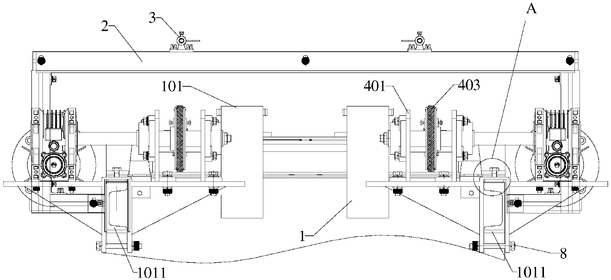
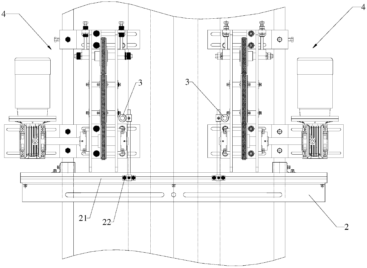
[0060] refer to figure 1 , this embodiment discloses a sheet material deviation correction device, including a conveying chassis 1, the conveying chassis 1 is provided with a support platform 101, the plate 7 is placed on the supporting platform 101 for transmission, and the conveying chassis 1 is provided with a detection area And the deviation correction area, the detection area is provided with a support beam 2 and two plate edge detectors 3, the support beam 2 is fixedly connected with the conveying chassis 1, the support beam 2 is perpendicular to the conveying direction of the conveying chassis 1, and the two plate edge detection The detectors 3 are arranged at intervals on the support beam 2 and symmetrically arranged along the center line of the conveying chassis 1, and the connection line of the edge detectors 3 of the two plates is perpendicular to the conveying direction of the conveying chassis 1.

[0061] In this embodiment, the board edge detector 3 is a photoele...

Embodiment 2

[0077] Based on Embodiment 1, the difference between this embodiment and Embodiment 2 is that in this embodiment, the supporting beam is located below the conveying chassis, the sheet edge detector is a travel switch, and the detecting end of the sheet edge detector points to the conveying chassis and Vertical to the lower surface of the conveying chassis, the distance between the detection end of the sheet edge detector and the conveying plane is less than the thickness of the sheet, so that when the sheet passes through the sheet edge detector, the sheet and the detection end of the sheet edge detector abut to trigger the sheet edge Detector.

Embodiment 3

[0079] This embodiment discloses a deviation correction method using the plate deviation correction device in Embodiment 1, including:

[0080] S1: The plate edge detector 3 detects the conveying state of the plate 7

[0081] If the plate 7 is conveyed to the bottom of the plate edge detector 3, and the plate edge detector 3 senses the plate 7 at the same time, then the plate 7 is transported normally, skip S2, and enter S3;

[0082] If the plate 7 is conveyed to the bottom of the plate edge detector 3, and the plate edge detector 3 does not sense the plate 7 at the same time, then the conveyance of the plate 7 is deviated, and enters S2, refer to Figure 8 ;

[0083] S2: Correction

[0084] refer to Figure 9 , if among the two groups of conveying components 4, the plate edge detector 3 on the side where one set of conveying components 4 is located first senses the plate 7, as shown in the figure, the plate edge detector 3 on the right side first detects the plate 7, Then...


PUM


Abstract

The invention discloses a plate deviation correction device and a deviation correction method. According to the scheme, the plate deviation correction device comprises a conveying underframe. A detection area and a deviation correction area are arranged on the conveying underframe. A supporting cross beam and two plate edge detectors are arranged in the detection area. The supporting cross beam isarranged above the conveying underframe. The plate edge detectors are symmetrically arranged along the center of the conveying underframe. Two sets of conveying assemblies symmetrically arranged along the center of the conveying underframe are arranged in the deviation correction area. The conveying assemblies independently operate to support plates to be conveyed forwards, the plate edge detectors detect the conveying state of the plates, and two sets of conveying belts support the plates to be conveyed forwards and independently operate. When deviation correction is needed, the operation speeds of the two sets of conveying assemblies are different by adjusting the operation speeds of the two sets of conveying assemblies, the operation state of the plates is adjusted through the speed difference between the two sets of conveying assemblies, and the aim of deviation correction is achieved. In the process of deviation correction, damage to the plates and the influence on the conveyingspeed of the plates are reduced.

Description

technical field [0001] The invention relates to the field of plate conveying, in particular to a plate deviation correcting device and a deviation correcting method. Background technique [0002] During the processing and manufacturing of plates such as ceramics, glass, and marble, due to factors such as uneven connections between machines or improper steering, the plates are inclined, and the inclined plates will not be conducive to subsequent processing. In order to arrange the plates neatly, facilitate the later processing and increase the output, a deviation correction device is required. [0003] In the prior art, the Chinese utility model patent with the notification number CN203612567U discloses an automatic deviation correction device in the ceramic tile conveying process, which includes a conveying platform, a left-right symmetrical primary and secondary correction mechanism; the primary correction mechanism includes a base, The rotating shaft, the fixed block, the...

Claims


Application Information

Patent Timeline
Patent Type & Authority Applications(China)
IPC IPC(8): B65G47/24
CPCB65G47/24
Inventor 黄佳生
Owner KEDA INDUSTRIAL GROUP CO LTD
Why Eureka
Try Eureka