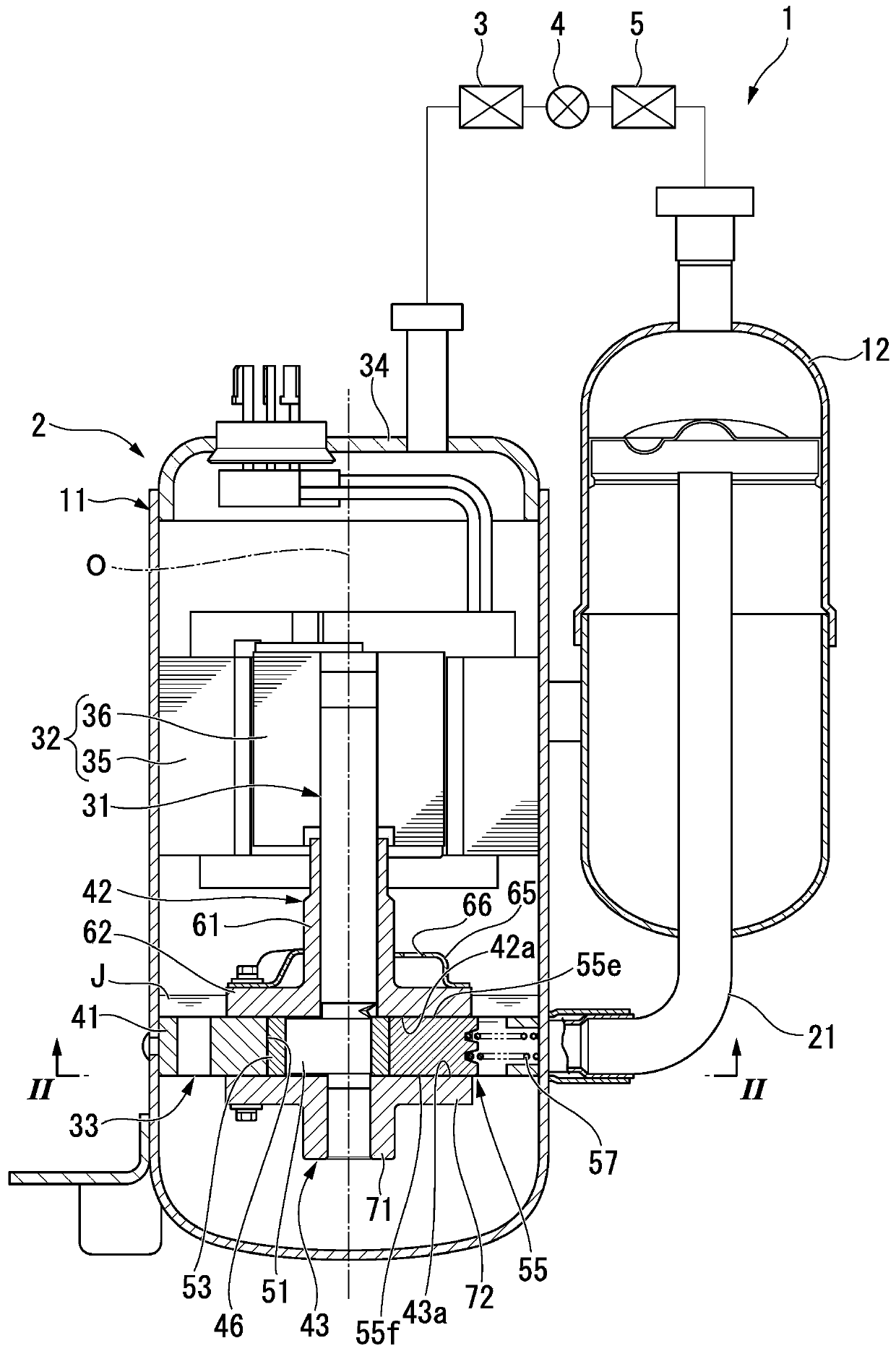
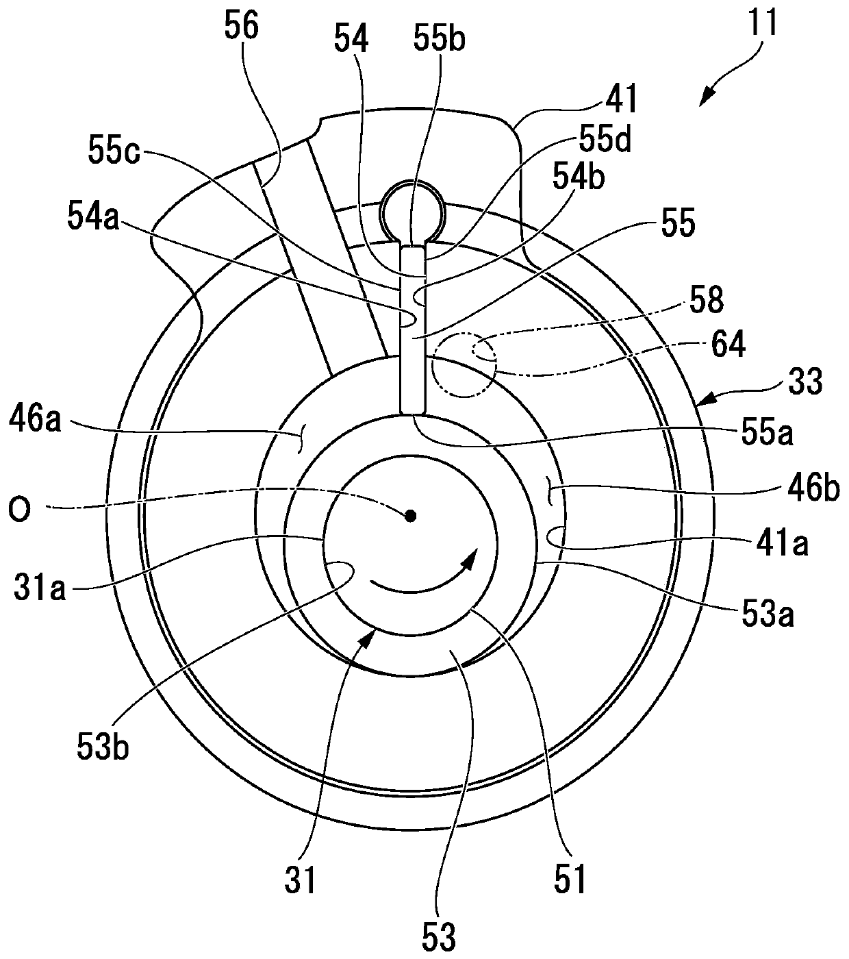
Compressor and refrigeration cycle device
A technology for compressors and compression mechanisms, which is applied to components, mechanical equipment, machines/engines, etc. of pumping devices for elastic fluids, and can solve problems such as difficulty in manufacturing compressors
- Summary
- Abstract
- Description
- Claims
- Application Information
AI Technical Summary
Problems solved by technology
Method used
Image

Examples
Embodiment 1
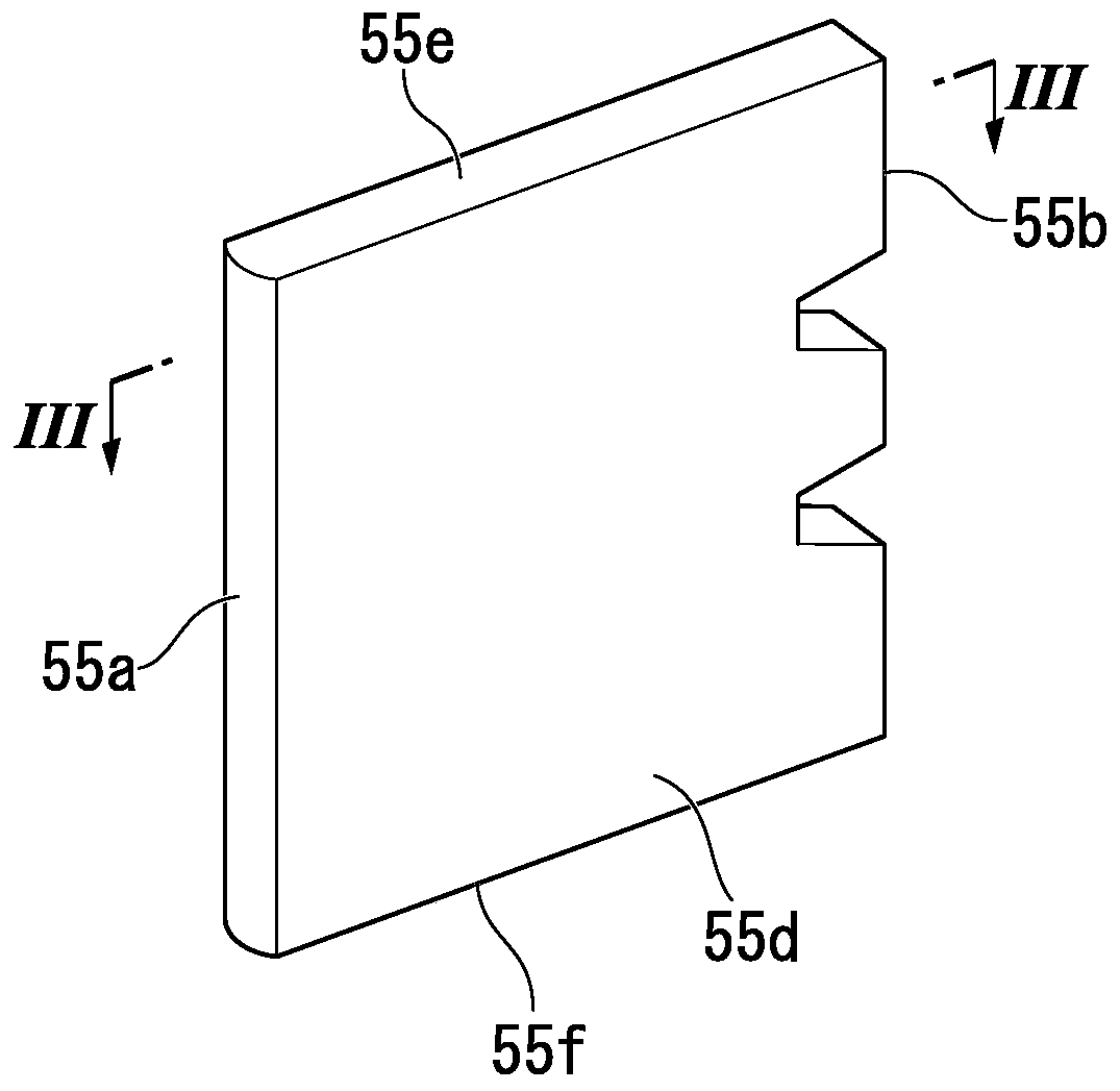
[0103] An example of a method of coating an oxide containing silicon on a sliding surface of a blade will be described. Will image 3 The blades (SUS440C) that have been subjected to gas nitriding treatment in the form exemplified in , were ultrasonically washed with a mixed solvent of acetone and hexane at a mass ratio of 1:1 for 30 minutes, followed by ultrasonic cleaning with chloroform for 30 minutes, and then washed with 2- Ultrasonic cleaning with propanol for 30 minutes, and treatment with UV ozone cleaner for 30 minutes. The washed leaves were immersed in 34.8 parts of ethanol.
[0104] A solution of 0.54 parts of tetraethoxysilane (TEOS) and 17.8 parts of ethanol was prepared in a sample container with a lid, and a solution of 1.3 parts of 28% ammonia water and 17.8 parts of ethanol was prepared in another sample container and mixed. The washed leaves were added to the mixed solution together with 34.8 parts of ethanol, and reacted at room temperature (25° C.) for 2...
Embodiment 2
[0112] The initiator immobilized leaf was obtained by the same method as in Example 1.
[0113] In a glove box, 0.00026 parts of ethyl-2-bromo-2-methylpropionate, lauryl methacrylate (SLMA, BLEMMER manufactured by NOF Corporation) were added to a pressure-resistant container made of Teflon (registered trademark). SLMA-S) 36.1 parts, copper (I) bromide 0.21 parts, copper (II) bromide 0.014 parts, 4,4'-dinonyl-2,2'-bipyridine 1.2 parts, anisole 37.5 parts. Next, put the immobilized blade of the initiator into a pressure-resistant container and cover it, and perform SI-ATRP at 600C and 400MPa for 2 hours. After the polymerization, the blades were taken out from the polymerization solution, washed thoroughly with THF, and the blades with thick-film PLMA brushes were obtained.
[0114] For the polymerization solution after polymerization, carry out 1 H-NMR measurement and the molecular weight measurement utilizing the GPC method calculate the Mn and Mw / Mn of free PLMA, and the re...
experiment example 1
[0129] These two-layer separation temperature diagrams from -10°C to 60°C when using HFC410A as a refrigerant as a working fluid and refrigeration machine oil as a polyol ester as a lubricant are shown in Figure 6 middle.
[0130] Such as Figure 6 As shown in , in the temperature range of -10°C to 60°C, there is a region where the working fluid (refrigerant) and the lubricant (refrigerator oil) are separated into two layers, but in the lubricant relative to the working fluid and the lubricating oil When the ratio of the total mass of the agents is 60% by mass or more, there is always compatibility.
PUM
 Abstract
Description
Claims
Application Information
 - R&D
- Intellectual Property
- Life Sciences
- Materials
- Tech Scout
- Unparalleled Data Quality
- Higher Quality Content
- 60% Fewer Hallucinations
Browse by: Latest US Patents, China's latest patents, Technical Efficacy Thesaurus, Application Domain, Technology Topic, Popular Technical Reports.
© 2025 PatSnap. All rights reserved.Legal|Privacy policy|Modern Slavery Act Transparency Statement|Sitemap|About US| Contact US: help@patsnap.com