Testing device and testing method of constant-power valve

A test device and constant power technology, applied in the direction of fluid pressure actuation device, fluid pressure actuation system test, mechanical equipment, etc., can solve the problems of high test cost, increased test difficulty, high test cost, and reduce test cost. , Test the effect of low energy consumption and compact structure

Pending Publication Date: 2019-04-09
青神格林维尔流体动力控制技术有限公司
View PDF5 Cites 0 Cited by
  • Summary
  • Abstract
  • Description
  • Claims
  • Application Information

AI Technical Summary

Problems solved by technology

At present, the constant power valve is installed on the hydraulic pump to test the adjustment performance of the constant power valve. The hydraulic pump consumes a lot of power during the test to test the constant power valve. This test consumes time and energy, and the test cost is relatively large. The installation of the power valve and the hydraulic pump is complicated and takes up space as a whole
There is also a constant power valve that is tested by manually turning the spool of the constant power valve to ensure that the output pressure of the constant power valve is 10 bar. However, manually turning the spool of the constant power valve increases the labor intensity of the workers and further increases Increased testing difficulty, resulting in high testing costs

Method used


Image

  • Testing device and testing method of constant-power valve
  • Testing device and testing method of constant-power valve
  • Testing device and testing method of constant-power valve

Examples


Embodiment Construction

[0021] The present invention will be further described below in conjunction with accompanying drawing, protection scope of the present invention is not limited to the following:

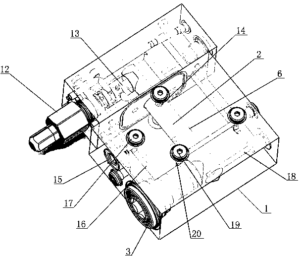
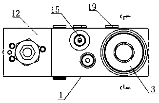
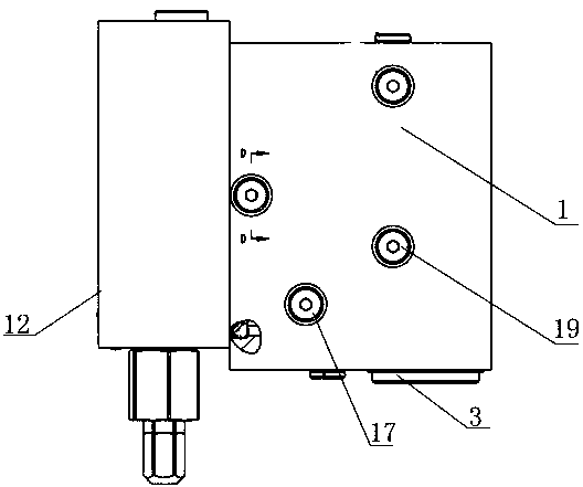
[0022] Such as Figure 1~6 As shown, a test device for a constant power valve, which includes a valve block 1, a swing rod 2, a plug 3 and a piston push rod 4, the front side of the valve block 1 is provided with a stepped hole 5 and a channel 6, and the stepped hole 5 Set perpendicular to the channel 6, the large hole of the stepped hole 5 is provided with an internal thread, the small hole of the stepped hole 5 is fixed with a sliding sleeve 7, and the left end cover 8 and the right end of the sliding sleeve 7 are respectively fixed at both ends of the sliding sleeve 7. The cover 9, the left end cover 8 and the right end cover 9 are provided with guide holes, and a piston push rod 4 is slidably installed between the two guide holes. The piston push rod 4 is fixed with a piston 11 that can slide alo...


PUM


Abstract

The invention discloses a testing device of a constant-power valve. The testing device comprises a valve block (1), a swing rod (2), a plug (3) and a piston push rod (4), wherein a step hole (5) and achannel (6) are formed in the front side of the valve block (1), the step hole (5) is arranged perpendicular to the channel (6), a sliding sleeve (7) is fixedly arranged in a small hole of the step hole (5), a left end cover (8) and a right end cover (9) are fixedly arranged in the sliding sleeve (7) and located at the two ends of the sliding sleeve (7), a piston (11) capable of sliding along thesliding sleeve (7) is fixedly arranged on the piston push rod (4), the piston (11) and the left end cover (8) form an oil return cavity, the piston (11) and the right end cover (9) form an oil inletcavity, and the left side of the valve block (1) is provided with the constant-power valve (12). The invention further discloses a testing method. The testing device and method have the beneficial effects that the structure is compact, testing is simple and convenient, the testing cost is reduced, the testing energy consumption is low, and the operation is simple.

Description

technical field [0001] The invention relates to the technical field of constant power valve performance testing, in particular to a testing device and a testing method for a constant power valve. Background technique [0002] Constant power valve is an important part of hydraulic system. At present, the constant power valve is installed on the hydraulic pump to test the adjustment performance of the constant power valve. The hydraulic pump consumes a lot of power during the test to test the constant power valve. This test consumes time and energy, and the test cost is relatively large. The installation of the power valve and the hydraulic pump is complicated and takes up space as a whole. There is also a constant power valve that is tested by manually turning the spool of the constant power valve to ensure that the output pressure of the constant power valve is 10 bar. However, manually turning the spool of the constant power valve increases the labor intensity of the worke...

Claims


Application Information

Patent Timeline
Patent Type & Authority Applications(China)
IPC IPC(8): F15B19/00
CPCF15B19/00
Inventor 张龙飞唐忠林
Owner 青神格林维尔流体动力控制技术有限公司
Why Eureka
Try Eureka