Air inlet plugging convenient combustion furnace
A technology of air inlet and combustion furnace, which is applied in the direction of combustion type, combustion equipment, combustion method, etc., can solve the problems of exhaust heat dissipation effect of fuel furnace, exhaust heat is not used, air inlet plugging and other problems, to achieve heat dissipation Adjustable effect, increased heat, convenient sealing effect
- Summary
- Abstract
- Description
- Claims
- Application Information
AI Technical Summary
Problems solved by technology
Method used
Image
Examples
Embodiment 1
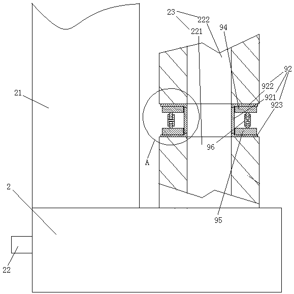
[0030] Embodiment one, see figure 1 and figure 2 , a combustion furnace with convenient air inlet plugging, comprising a furnace body 2. The furnace body is provided with a chimney 21 , an air inlet 22 and a gaseous fuel inlet 23 .
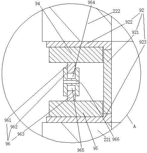
[0031] The air inlet 22 includes a lower section 221 of the air inlet and an upper section 222 of the air inlet arranged sequentially from bottom to top. The lower section 221 of the air inlet is integrally formed and hermetically connected with the main body. The upper end of the air inlet upper section 222 is connected with the outlet of the blower. A seal 92 is provided between the lower section 221 of the air inlet and the upper section 222 of the air inlet. The seal 92 is located between the lower end surface of the upper section of the air inlet and the upper end surface of the lower section of the air inlet. The seal includes a rigid connecting pipe 921, an upper rubber sealing gasket 922 integrally formed on the upper end of the rigi...
Embodiment 2
[0033] Embodiment two, the difference with embodiment one is:
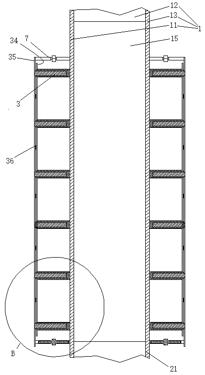
[0034] see image 3 , Figure 4 and Figure 5 , the upper end of the chimney 32 is fixedly connected with the cooling section 1 . The heat dissipation section is surrounded by a left wall 11 , a front wall 12 , a right wall 13 and a rear wall 14 . A plurality of aluminum plates 15 extending along the extending direction of the heat dissipation section are provided in the heat dissipation section. The aluminum plates are distributed along the front and rear directions. The aluminum plate is connected with the inner surface of the left wall. Radiating plates 3 are provided on the outer surfaces of the left wall 11 , the front wall 12 , the right wall 13 and the rear wall 1 . The cooling plate is a flat structure. The heat dissipation plate extends along a direction perpendicular to the axial direction of the heat dissipation section. The heat dissipation plates are distributed along the axial direction of th...
Embodiment 3
[0036] Embodiment three, the difference with embodiment two is:
[0037] see Figure 6 , the chimney jacket is provided with a middle pipe 4. The outer tube 5 is arranged on the outer tube of the middle tube. A fuel chamber 41 is formed between the middle pipe and the exhaust pipe. The fuel chamber is provided with a spiral guide piece 42 with the center line of the chimney as the center line. The spiral guide piece forms a spiral gas channel 43 in the fuel chamber. One end of the gas passage is connected with the gas fuel inlet 23 , and the other end is connected with the outlet of the fuel delivery pump 44 . The part of the chimney inside the middle pipe is made of heat-conducting material. An air chamber 51 is formed between the outer tube and the middle tube. One end of the air chamber is connected with the upper end of the upper section 222 of the air inlet, and the other end is connected with the outlet of the blower 52, thereby realizing the connection between the...
PUM
 Abstract
Description
Claims
Application Information
 - R&D
- Intellectual Property
- Life Sciences
- Materials
- Tech Scout
- Unparalleled Data Quality
- Higher Quality Content
- 60% Fewer Hallucinations
Browse by: Latest US Patents, China's latest patents, Technical Efficacy Thesaurus, Application Domain, Technology Topic, Popular Technical Reports.
© 2025 PatSnap. All rights reserved.Legal|Privacy policy|Modern Slavery Act Transparency Statement|Sitemap|About US| Contact US: help@patsnap.com


