Pipe connecting device

A technology for connecting devices and pipe fittings, applied in the direction of sleeve/socket connection, pipe/pipe joint/pipe fitting, through components, etc., can solve problems such as equipment damage, seal rupture, uneven seal, etc.

Inactive Publication Date: 2002-12-11
SAINT GOBAIN PAM SA
View PDF5 Cites 0 Cited by
  • Summary
  • Abstract
  • Description
  • Claims
  • Application Information

AI Technical Summary

Problems solved by technology

In the initial installed state, the smooth cannula does not enter along the axis of the socket, causing unevenness of the seal
This can lead to equipment damage and even rupture of the seal, especially when the misalignment between the shafts is greater than 3 degrees

Method used


Image

  • Pipe connecting device
  • Pipe connecting device
  • Pipe connecting device

Examples


Embodiment Construction

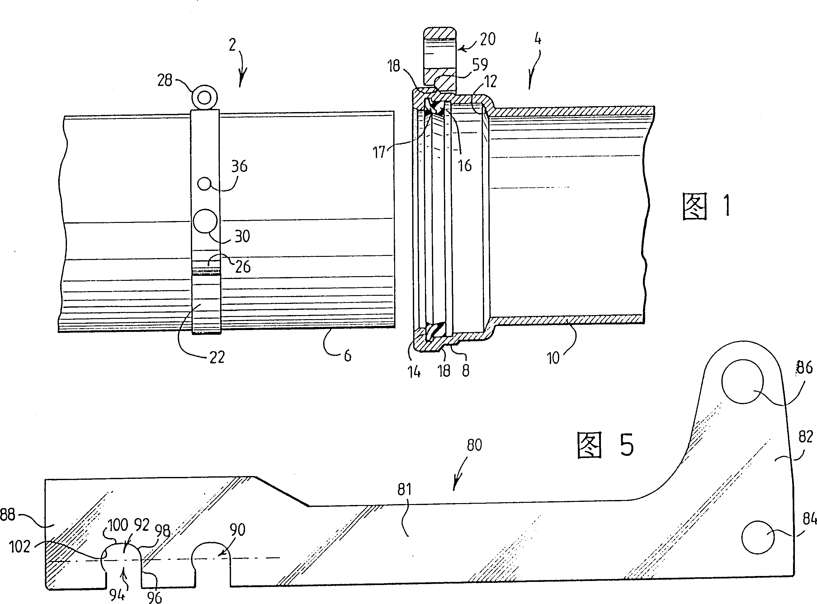
[0041] As shown in FIG. 1 , the invention consists in connecting a first pipe 2 into a second pipe 4 .

[0042] The connection of the two pipes is ensured by introducing the smooth cylindrical end (also called smooth cannula) 6 of the pipe 2 into the corresponding socket 8 of the pipe 4 .

[0043] The socket 8 has a diameter greater than the diameter of the body 10 of the pipe 4 and also has an axial boss 12 at the bottom against which the smooth cannula 6 abuts after the connection operation has been completed.

[0044] The socket also has an inner groove 14 for receiving an annular seal 16 . This seal, for example the seal described in FR-A-2679622 and the seal of specification Vi sold by the company PONT-A-MOUSSON, have a metal locking insert 17 that locks when the two pipes are connected. Hold the two fittings assembled.

[0045] There is also an annular shoulder 18 on the outside of the socket tube 8, and the supporting member 20 shown in the figure is next to the shoul...


PUM


Abstract

The connection for piping components (4) respectively at the smooth end and at the fitting (8) containing a radial compression seal comprises the following parts. A first support (22) integral with the first piping component comprises a operating crank (38). A second support part (20) is fixed to the second piping component (4). A rod engages with one end of the crank and pivots on the second support, particularly by engaging a hole (84) in the rod with a pivot pin (62) in the external periphery of the second support. The rod and the second support comprise associated stops (64,104,106) which limit the rod pivoting relative to the support.

Description

technical field [0001] The invention relates to a pipe fitting connecting device for a smooth intubation tube and a socket tube, the socket tube has a radial pressure-resistant seal, and the device comprises; [0002] - a first support mechanism connected to the first pipe and having at least one handle; [0003] - a second support mechanism connected to the second pipe, and [0004] - at least one link, which on the one hand cooperates with the end of the handle and on the other hand rotates about an axis on the second supporting means, in particular by making a hole in the connecting rod cooperating with said second supporting means After the journals on the outer circumference fit together, the connecting rod rotates around the axis. Background technique [0005] Usually, the two pipes are connected by introducing the smooth cylindrical end or smooth cannula of the first pipe into the corresponding socket of the second pipe, and there is a seal in the socket, when the c...

Claims


Application Information

Patent Timeline
Patent Type & Authority Patents(China)
IPC IPC(8): F16L1/10F16L21/08F16L21/025F16L1/09
CPCF16L1/10F16L21/08F16L1/09
Inventor B·格尔施J·L·德莫伊森R·鲍金D·勒斯克特
Owner SAINT GOBAIN PAM SA
Why Eureka
Try Eureka