Intelligent oil pumping control method and intelligent oil pumping unit

An intelligent control and pumping unit technology, applied in earthwork drilling, mechanical equipment, machines/engines, etc., can solve problems such as inability to automatically adjust the balance, the inability to automatically adjust the stroke times, and the mismatch between the stroke times and the oil production of the oil well

Active Publication Date: 2015-07-15
XINJIANG UYGUR AUTONOMOUS REGION NO 3 MACHINE TOOL WORKS
View PDF5 Cites 35 Cited by
  • Summary
  • Abstract
  • Description
  • Claims
  • Application Information

AI Technical Summary

Problems solved by technology

[0003] The present invention provides an intelligent control oil pumping method and an intelligent pumping unit, which overcomes the deficiencies in the prior art above, and can effectively solve the problem that the existing beam pumping unit cannot automatically adjust the flushing times and c

Method used


Image

  • Intelligent oil pumping control method and intelligent oil pumping unit
  • Intelligent oil pumping control method and intelligent oil pumping unit
  • Intelligent oil pumping control method and intelligent oil pumping unit

Examples


Embodiment 1

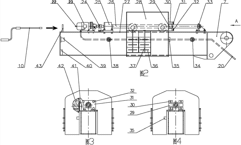
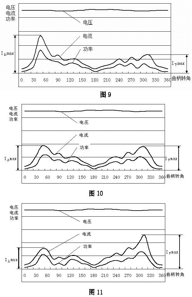
[0046] Embodiment 1, as attached Figure 6 , 7 , shown in 8, this intelligent control oil pumping method comprises intelligent pumping unit, and this intelligent pumping unit comprises main motor 15, beam 3, balance boom 7, crank 9 and rope suspension device 1; A balance boom 7 is fixedly installed on the left end, and a mobile counterweight box 28 and a driving device capable of moving the mobile counterweight box 28 left and right are respectively installed on the balance boom 7, and a central processing unit and a three-phase electrical parameter acquisition device are also included. The three-phase electric parameter acquisition device is installed on the power supply input end; a frequency converter is installed between the main motor 15 and the power supply input end, and a load sensor 17 is fixedly installed on the rope hanger 1 for collecting the suspension point load value F. A stroke process measuring device is installed on the intelligent pumping unit to collect...

Embodiment 2

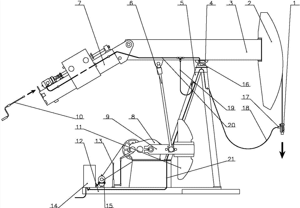
[0105] Embodiment 2, as attached figure 1 , 2 , 3, and 4, the intelligent pumping unit includes a main motor 15, a reducer 8, a crank 9, a connecting rod 6, a beam 3, a balance boom 7, a support 5, a donkey head 2, a base 12, and a braking device 13 , rope hanging device 1 and stroke process measuring device; main motor 15, speed reducer 8, braking device 13 and support 5 are fixedly installed on base 12, and the beam 3 that can swing up and down is hinged on the beam support 4 in the middle On the top of the bracket 5, a crank 9 is installed on the power output shaft of the reducer 8, the lower end of the connecting rod 6 is hinged with the crank 9, the upper end of the connecting rod 6 is hinged on the left part of the beam 3, and the right end of the beam 3 A donkey head 2 is fixedly installed, a rope suspension device 1 is installed on the donkey head 2, a balance boom 7 is fixedly installed on the left end of the beam 3, and a mobile counterweight box 28 and a movabl...


PUM


Abstract

The invention relates to the technical field of beam-pumping units, in particular to an intelligent oil pumping control method and an intelligent oil pumping unit. The intelligent oil pumping unit comprises a main motor, a speed reducer, a crank, a connecting rod, a walking beam, a balance lifting arm, a bracket, a horse head, a base, a brake device, a beam hanger, a load sensor, a strole process measurer, a safety limiting device and a digital control cabinet, has the characteristics of safety and reliability, realizes the intelligent optimization and adjustment of stroke times and balance of the oil pumping unit, fully exerts the well yield, improves the oil pumping unit well system efficiency, is in seamless joint with an oil field computer network system to realize the data remote transmission and the remote switch well control, simplifies the operation, is convenient and fast, saves the labor, saves the energy, reduces the emission, and improves the economic benefit.

Description

technical field [0001] The invention relates to the technical field of beam pumping units, and relates to an intelligent control oil pumping method and an intelligent pumping unit. Background technique [0002] The existing beam pumping units mainly include: conventional beam pumping unit, front beam pumping unit, offset beam pumping unit and special-shaped beam pumping unit, etc. The beam pumping unit generally includes a donkey head, a beam, a bracket, a connecting rod, a base, a crank, a balance device, a reducer, a brake, a motor and a rope hanger, and a bracket, a reducer, a brake, Motor and control cabinet, etc., the beam is hinged on the bracket, the crank is fixed on the output shaft of the reducer, one end of the connecting rod is hinged on the crank, and the other end of the connecting rod is hinged on the beam, thus forming a four-bar linkage Mechanism, the donkey head is installed on the front end of the beam, the rope hanger is installed on the donkey head; the...

Claims


Application Information

Patent Timeline
IPC IPC(8): E21B43/00
CPCE21B43/12E21B43/00F04B47/02
Inventor 于胜存胡广杰高长乐岳军梁尚斌马述俭程晓军赵普春姜传方郭强吕志强李绍奇
Owner XINJIANG UYGUR AUTONOMOUS REGION NO 3 MACHINE TOOL WORKS
Why Eureka
Try Eureka