Bicycle propulsion system

a propulsion system and bicycle technology, applied in the direction of steering devices, cycle equipments, vehicle components, etc., can solve the problem of providing primary exercise to the lower part of the rider's body, and achieve the effect of reliable and positive steering for

Active Publication Date: 2006-02-21
CAPEK WILLIAM
View PDF5 Cites 34 Cited by
  • Summary
  • Abstract
  • Description
  • Claims
  • Application Information

AI Technical Summary

Benefits of technology

[0005]Accordingly, a primary object of the present invention is to provide a bicycle mechanism that enables upper body steering and propulsion, wherein the steering mechanism enables a reliable and positive force for steering the bicycle to conventional usage, and yet a non-fowling structure for the lower body of the user after disconnect.
[0007]These and other objects of the present invention are provided in a structure and mechanism for a bicycle which features basic elements of a conventional two-wheel bicycle, such as a pair of pedals mounted through a sprocket to the rear wheel of the bicycle, a diagonal frame piece, a horizontal frame piece and a steering fork for the front wheel. Mounted atop the steering fork is a rotatable circular steering disk, steering links, rotatably attached to the disk, and at the other ends of the steering links, conventional handles are attached so that a rotating motion of the handles turns the disk and thereby steers the front wheel of the bicycle. At the other ends of the levers mounting the handles, power links are provided and connected to the pedals of the bicycle, with a disconnecting capability. The levers are provided with a fulcrum at approximately their midpoints on the horizontal frame piece, where the levers are split approximately in half to enable a steering motion by twisting the handles. Such a split enables the use of a collar to isolate the steering motion.

Problems solved by technology

One drawback of the usual bicycle linkages relates to the fact that with such linkages, the primary exercise is provided to the lower part of the rider's body.

Method used


Image

  • Bicycle propulsion system
  • Bicycle propulsion system
  • Bicycle propulsion system

Examples


Embodiment Construction

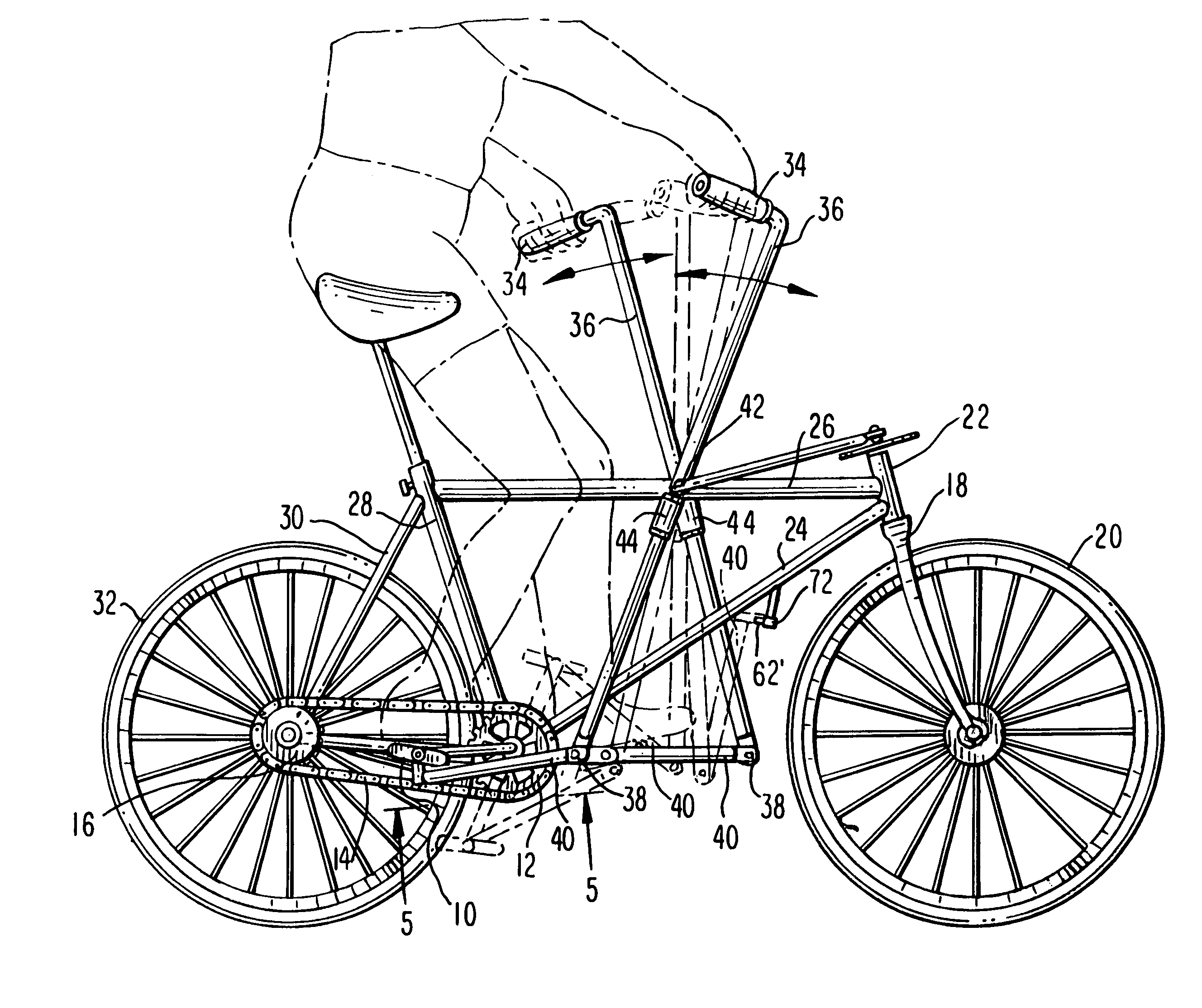
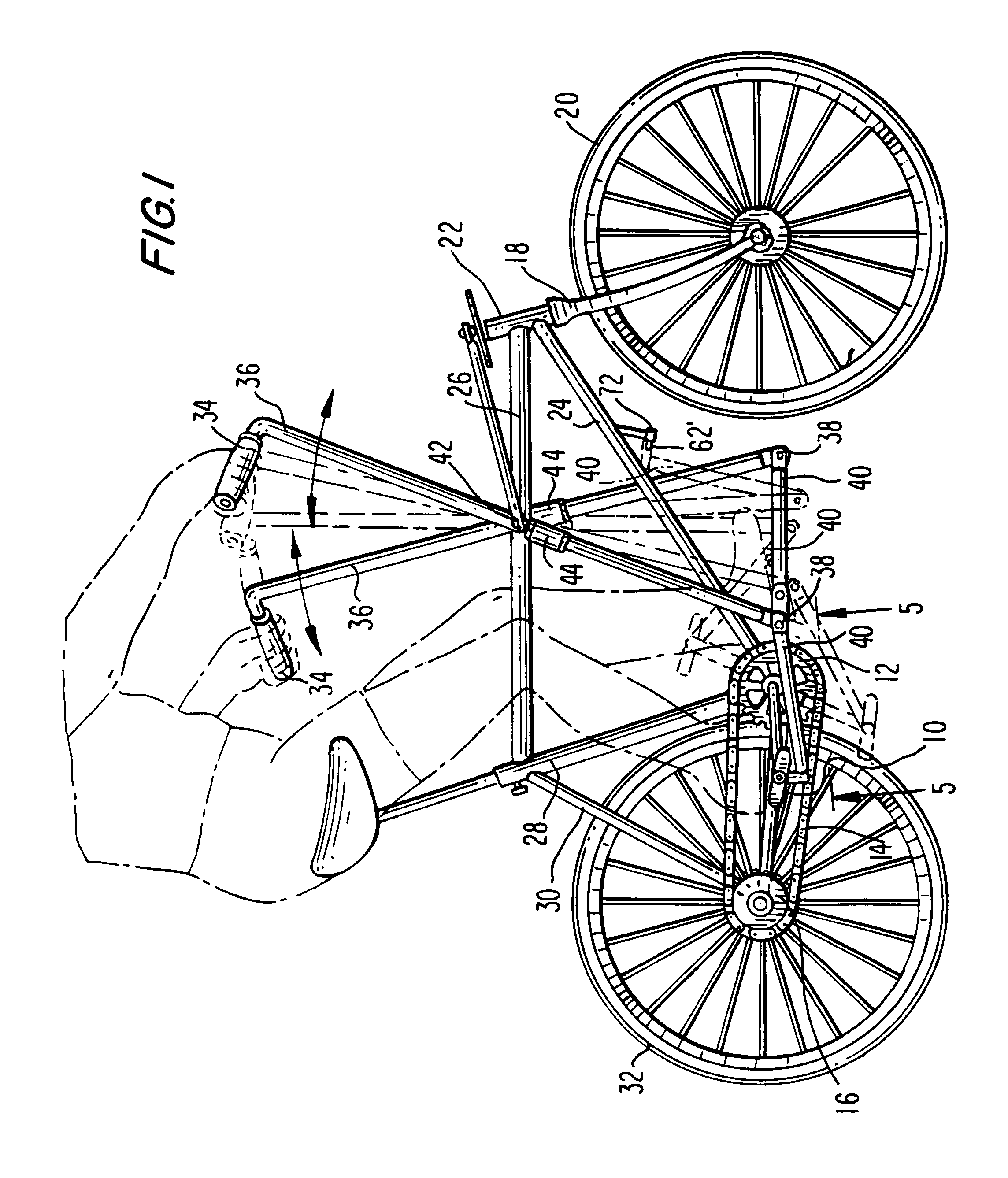
[0016]Referring to the drawings, and particularly FIG. 1 thereof, the elements of a typical two-wheel bicycle design are shown. Pedals 10 are used to power the bicycle by connection to sprocket 12 which mounts chain 14 to rear wheel sprocket 16, and for operation in the conventional manner for two-wheel bicycles. A steering fork 18 is mounted astride the center of the front wheel 20 for steering by motion within the tube 22 at the top of fork 18. The conventional and the present invention bicycles also have a diagonal frame piece 24 and horizontal frame piece 26, with seat mount frame piece 28 and the rotatable frame piece 30, rotatably connected to rear wheel 32. Handles 34 are also provided, but in the present invention connected to levers 36, and at the top thereof. Such levers at the bottom ends thereof are connected by swivel joints 38 to power links 40. Such power links 40 are formed and arranged to connect and disconnect from pedals 10, as will be described hereinafter with r...


PUM


Abstract

The disclosure herein provides a two-wheel bicycle system wherein a pair of long levers are arranged on the cross-beam of the frame, to provide the fulcrum for the motion of the levers. The tops of the levers comprise handles perpendicular to such levers, with linkages to a circular and rotatable crank, which rotates in a plane parallel to the ground about a column commonly found in the steering mechanism for such a bicycle. The bottom ends of the levers connect to linking members to connect such levers to the pedals commonly found in such a bicycle. Such linking members are provided so that they are disconnected and then rotatable to be mounted on the diagonal frame piece of the bicycle, when the bicycle is used with hand-operated steering and foot-operated power. Before disconnection, only upper body energy is used to control both steering and powering the bicycle.

Description

FIELD OF THE INVENTION[0001]This invention relates primarily to two-wheel bicycle designs, and more particularly to a bicycle and link design that enables upper body motion to both propel and to steer the bike; and yet, with a simple disconnect and storage mounting of a link element, the overall design is restored so that the bike is steered with the upper body and propelled by the lower body of the user.BACKGROUND OF THE INVENTION[0002]Bike riding, for many years, has been used for providing play value to a youngster, but also for providing exercise to both youngsters and oldsters. One drawback of the usual bicycle linkages relates to the fact that with such linkages, the primary exercise is provided to the lower part of the rider's body. In other words, a much lesser amount of exercise is provided to the arms, as compared to the legs.[0003]Attempts have been made to more evenly distribute the arms / legs exercise.[0004]More even distribution of arms / legs exercise has been attempted ...

Claims


Application Information

Patent Timeline
IPC IPC(8): B62M1/04B62M1/24
CPCB62M1/12
Inventor CAPEK, WILLIAM
Owner CAPEK WILLIAM
Why Eureka
Try Eureka