
Method for simulating sea waves by using barrel-type centrifugal machine and apparatus therefor

A centrifuge and special device technology, applied in the field of simulated ocean waves, can solve the problems of poor test operability and small range of simulated wave parameters, etc., and achieve the effects of easy operation, wide frequency range and good wave elimination effect

Inactive Publication Date: 2005-01-19
INST OF MECHANICS - CHINESE ACAD OF SCI
View PDF1 Cites 36 Cited by
  • Summary
  • Abstract
  • Description
  • Claims
  • Application Information

AI Technical Summary

Problems solved by technology

[0005] The purpose of the present invention is to: overcome the deficiencies such as the small range of simulated wave parameters and poor test operability of the existing beam-type centrifuge wave generating device, thereby providing a method and device for simulating sea waves with a drum-type centrifuge

Method used


Image

  • Method for simulating sea waves by using barrel-type centrifugal machine and apparatus therefor
  • Method for simulating sea waves by using barrel-type centrifugal machine and apparatus therefor
  • Method for simulating sea waves by using barrel-type centrifugal machine and apparatus therefor

Examples


Embodiment 1

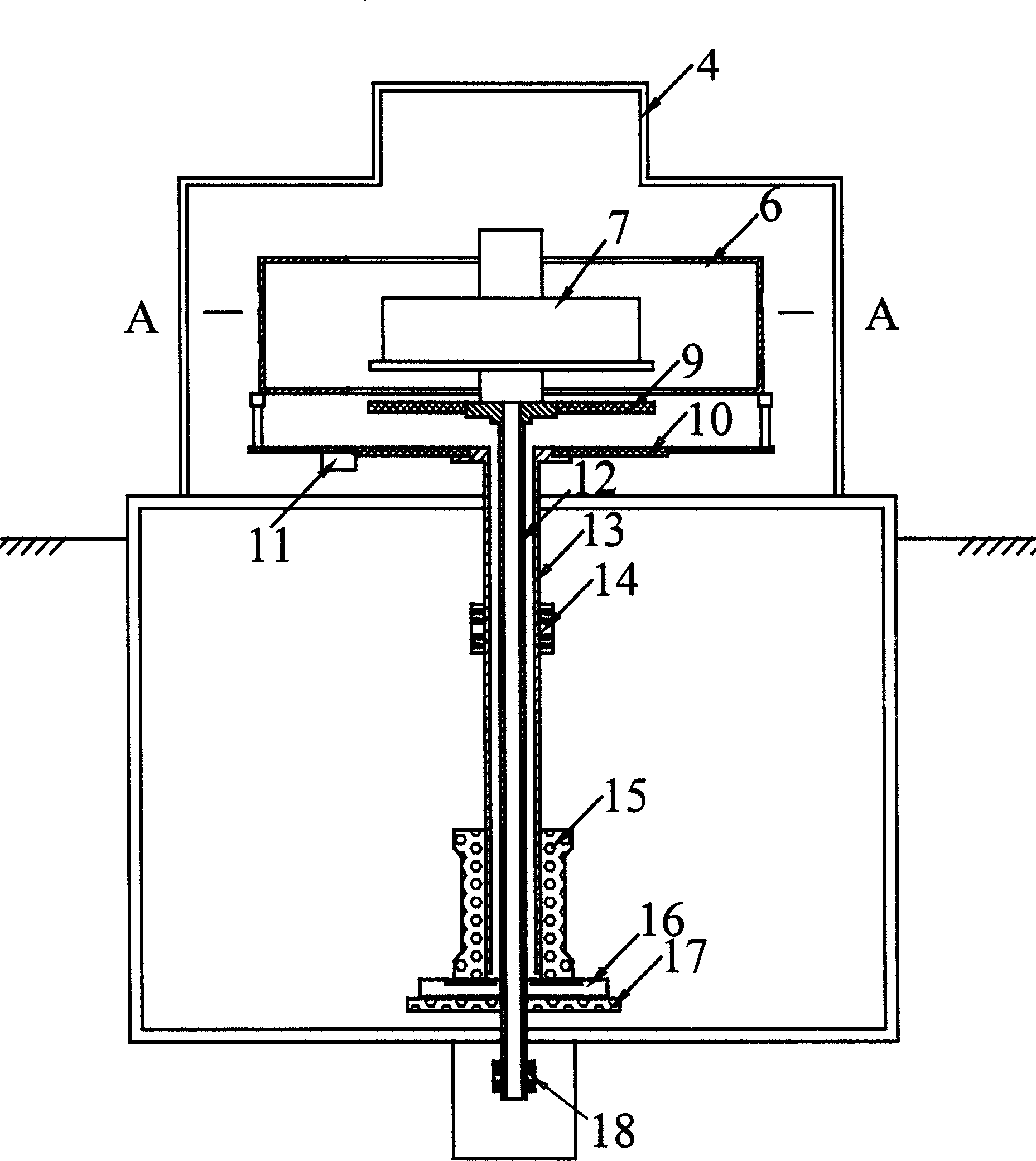
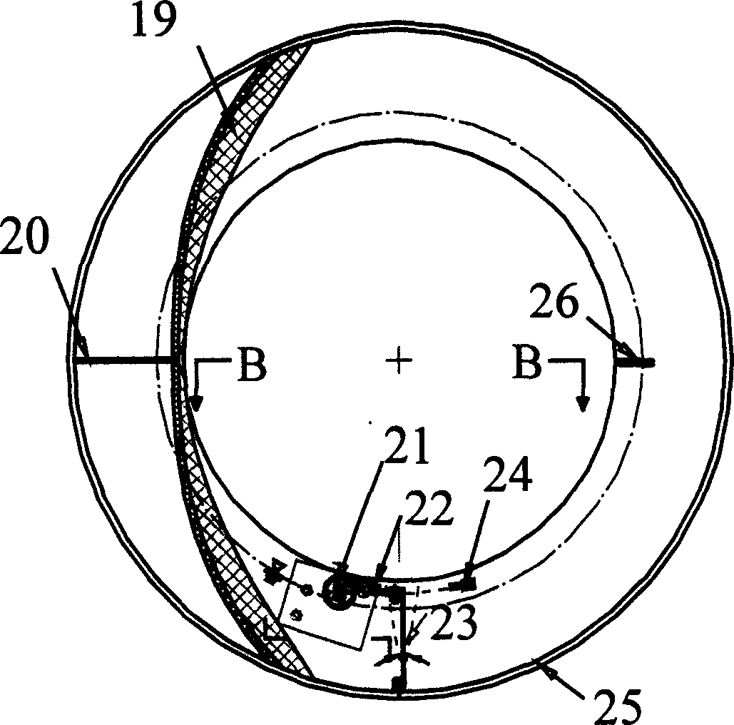
[0044] Make a special device for simulating ocean waves with a drum centrifuge, as attached figure 1 , 3 , 4, and 5. The device is composed of drum centrifuge and wave making device.

[0045] as attached figure 1 and image 3As shown, the drum-type centrifuge includes: a protective cover 4, a drum-shaped groove 6 located in the protective cover 4, a central console 7 located in the drum-shaped groove 6, a lifting device 8 on the central console 7, a central console support Board 9, drum-shaped groove support 10, digital acquisition computer 11 installed at the bottom of drum-shaped groove support 10, inner shaft 12 connected with center console support 9, outer shaft 13 connected with drum-shaped groove support 10 , the first servo motor 15 for driving the outer shaft 13, the second servo motor 17 for driving the inner shaft 12, a clutch transmission 16 is also arranged between the inner shaft 12 and the outer shaft 13, and the A first slip ring 14 and a second slip ring ...

Embodiment 2

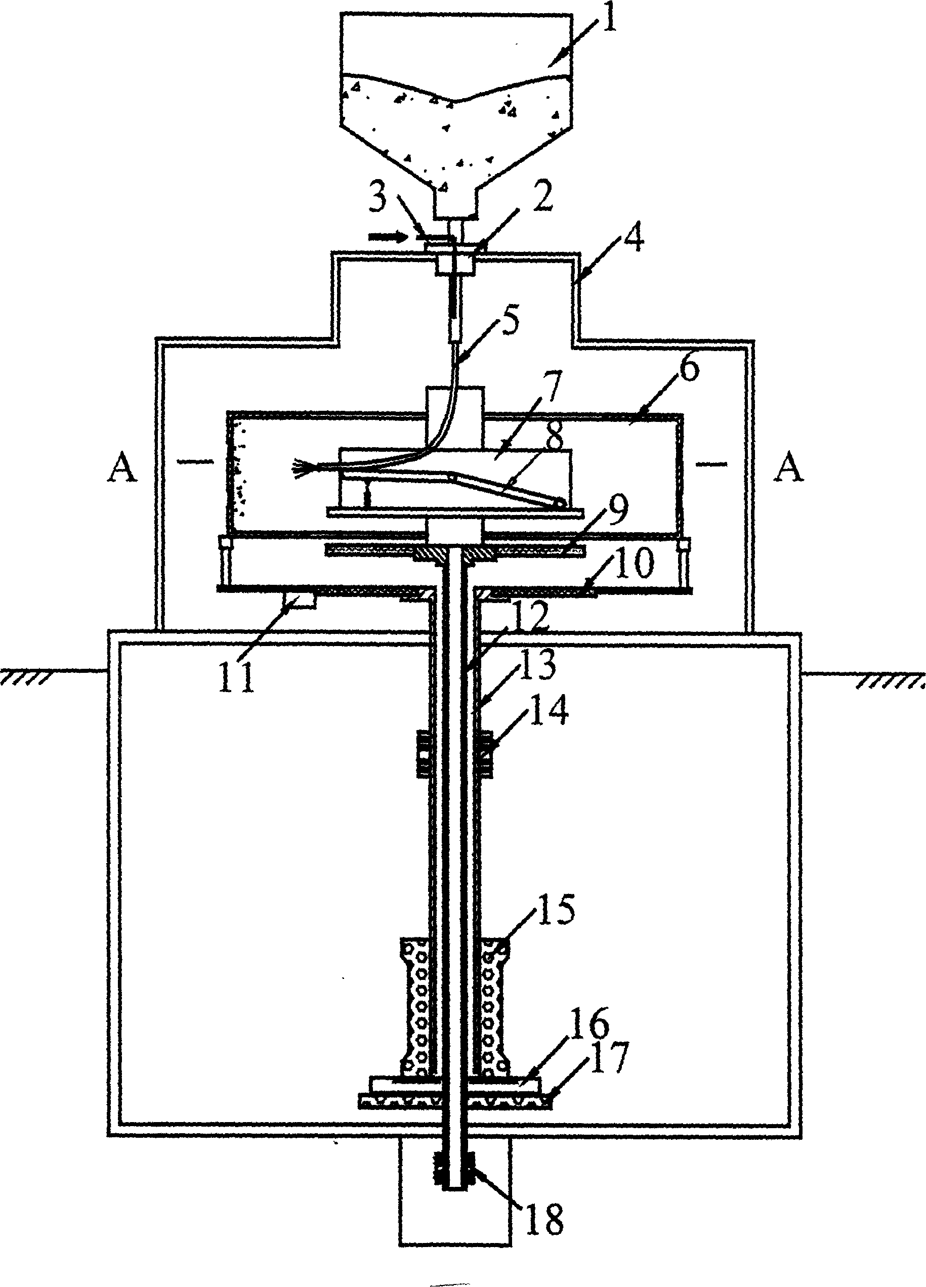
[0055] Make a special device for simulating ocean waves with a drum centrifuge, as attached figure 2 , 3 , 4, and 5. The device is composed of drum centrifuge, wave making device and sand sample preparation device.

[0056] Such as figure 2 As shown, the sand sample funnel 1 is fixed on the protective cover of the drum centrifuge through the steering knuckle 2, and the sand conduit 5 communicates with the sand sample funnel 1 through the compressed air conduit 3. Under the action of compressed air, the sand in the sand conduit 5 Soil is more convenient to flow in the centrifuge drum groove 6, and the lower outlet of sand conduit 5 is installed on the hoisting device 8 that is positioned at the center console 7 of drum type centrifuge, and the lower outlet of sand conduit 5 both can follow central control The table 7 rotates together, and can reciprocate along the axial width direction of the drum-shaped groove 6 together with the lifting device 8 on the central console 7,...


PUM

PropertyMeasurementUnit
Radial depthaaaaaaaaaa
Axial widthaaaaaaaaaa

Abstract

This invention relates to a method and apparatus for imitating sea wave by use of a drum-type centrifuge. The method is the following: to feed water into the drum type groove through the water input system of the centrifuge when it achieves stated centrifugal acceleration; to start the wave generator located in inside wall of the groove to generate moving wave; then to absorb wave through the wave breaker located on the other end of the inside wall. The said apparatus comprises drum-type centrifuge and wave generator and is characterized by the following: the wave generator is located inside the drum type groove with a external diameter of one to three meter, radial depth of twenty to fifty centimeter, axial width twenty to forth centimeter. The said wave generator comprises a crank swing mechanism made up of crank wheel, connecting bar and swing board and servomotor. The said wave breaker is located on side wall of the groove near to swing board with a baffle board in the middle.

Description

technical field [0001] The invention relates to a sea wave simulation technology used in marine geotechnical engineering, offshore structural engineering and water conservancy engineering, in particular to a method and device for simulating sea waves with a drum type centrifuge. Background technique [0002] The basic principle of centrifugal simulation technology is to reduce the prototype material by N times according to the principle of geometric similarity to prepare a model, and put it in the centrifugal force field of N times the acceleration of gravity generated by the centrifuge for testing, so that the model can reach the same stress state as the prototype. Using this technology, it is possible to observe and study gravity-related geotechnical engineering and other issues in the prototype stress state, especially to study the failure and instability problems in engineering, which is difficult for prototypes. [0003] Geotechnical centrifugal simulation technology ha...

Claims


Application Information

Patent Timeline
IPC IPC(8): E02B1/02G01M10/00
Inventor 高福平吴应湘
Owner INST OF MECHANICS - CHINESE ACAD OF SCI
Learn More