Flow velocity measurement method applied to radar wave flow velocity meter and radar wave flow velocity meter

A flow velocity measurement and flow velocity meter technology, applied in the field of flow velocity instruments, can solve the problems of electromagnetic wave transmitting and receiving signals, affecting the electromagnetic wave receiving frequency, affecting the measurement accuracy of radar wave velocity instruments, etc., so as to improve the accuracy and the calculation accuracy. Effect

Active Publication Date: 2019-04-09
北京奥特美克科技股份有限公司
View PDF19 Cites 3 Cited by
  • Summary
  • Abstract
  • Description
  • Claims
  • Application Information

AI Technical Summary

Problems solved by technology

[0004] (1) The vibration of the radar wave current meter itself affects the measurement accuracy
For example, radar current meters installed under bridge decks are highly susceptible to vibrations from passing vehicles
The frequency generated by the vibration can easily affect the receiving frequency of electromagnetic waves, thereby affecting the measurement accuracy of the radar wave velocity meter
The radar current meter installed on the crossbar of the river bank is affected by the strong wind and vibrates, which is more likely to affect the receiving frequency of electromagnetic waves
[0005] (2) Weather factors affect the measurement accuracy of the radar current meter
For example, weather such as strong winds and rainstorms will have a certain impact on the emission and reception of electromagnetic waves, which in turn will affect the measurement accuracy of the radar wave velocity meter

Method used


Image

  • Flow velocity measurement method applied to radar wave flow velocity meter and radar wave flow velocity meter
  • Flow velocity measurement method applied to radar wave flow velocity meter and radar wave flow velocity meter
  • Flow velocity measurement method applied to radar wave flow velocity meter and radar wave flow velocity meter

Examples


Embodiment Construction

[0047] The technical solutions in the embodiments of the present invention will be clearly and completely described below in conjunction with the accompanying drawings in the embodiments of the present invention. Obviously, the described embodiments are only a part of the embodiments of the present invention, rather than all the embodiments. Based on the embodiments of the present invention, all other embodiments obtained by those of ordinary skill in the art without creative work shall fall within the protection scope of the present invention.

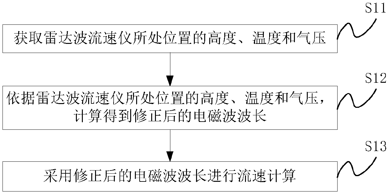
[0048] The embodiment of the present invention provides a flow velocity measurement method applied to a radar wave velocity meter, see figure 1 , The flow rate measurement method may include the steps:

[0049] S11: Obtain the altitude, temperature and pressure of the position where the radar wave velocity meter is located.

[0050] In a specific embodiment, the altitude sensor is set to collect the altitude of the position where the radar w...


PUM


Abstract

The invention provides a radar wave flow velocity meter and a flow velocity measurement method applied to the radar wave flow velocity meter. A corrected electromagnetic wavelength is obtained throughcarrying out calculation according to a height, a temperature and air pressure of a position where the radar wave flow velocity meter is located, and the corrected electromagnetic wavelength is utilized to carry out flow velocity calculation, so that the flow velocity calculation correctness is improved. Furthermore, vibration interference signals in electromagnetic wave reception signals are filtered, so that the Doppler frequency value calculation correctness is improved and then the flow velocity calculation correctness is improved. By utilizing a related Fourier transform algorithm, high-precision Doppler frequency values can be calculated under limited sampling point data, so that the flow velocity calculation result can be accurate to 0.1 mm/s.

Description

Technical field [0001] The invention relates to the technical field of flow meters, and more specifically, to a flow rate measurement method applied to a radar wave flow meter and a radar wave flow meter. Background technique [0002] Currently, the measurement of river flow velocity usually uses a flow meter. The flow meter is mainly divided into four types: mechanical, electrical, ultrasonic and radar wave. Mechanical, electrical and ultrasonic are contact measurement methods. Radar waves are non-contact measurement. The radar wave velocity meter is based on the Doppler principle to measure the water flow velocity. When the electromagnetic wave emitted by the radar wave velocity meter illuminates the flowing water surface, the receiving frequency of the radar will change due to the Doppler effect. When the direction of the velocity of the water surface coincides with the direction of the electromagnetic wave, the received frequency increases. When the direction of surface ...

Claims


Application Information

Patent Timeline
Patent Type & Authority Applications(China)
IPC IPC(8): G01P5/00
CPCG01P5/00
Inventor 李献吴玉晓高霏李海增刘瑞锋任建国
Owner 北京奥特美克科技股份有限公司
Why Eureka
Try Eureka