Method and device for forming stepped cylindrical member through laser impact

A technology of laser shock and cylindrical parts, which is applied in the forming of high-precision complex shape parts, and the field of laser shock forming stepped cylindrical parts, which can solve the problems of failure to improve the forming depth of metal sheets, exceeding the forming speed of metal sheets, and limiting metal sheets Formability and other issues can be achieved to reduce thermal effects, save processing time, and improve impact effects

Active Publication Date: 2019-04-12
ANHUI UNIVERSITY OF TECHNOLOGY
View PDF12 Cites 4 Cited by
  • Summary
  • Abstract
  • Description
  • Claims
  • Application Information

AI Technical Summary

Problems solved by technology

Since the direction of the laser shock wave force induced by laser irradiation is along the axis of the optical axis, it is difficult for the thin plate to fill the fillet of the mold during the forming process, especially for the deep part forming, and the forming quality is poor
In order to obtain a larger forming depth, a high-energy pulsed laser beam is often used to complete the forming of the metal sheet, and the resulting problem is: On the one hand, the excessive laser energy causes the reverse plasticity of the metal sheet after the collision with the die. Deformation reduces the forming quality; on the other hand, the excessive impact energy makes the forming speed of the metal sheet exceed the limit value, and the bottom of the formed part cracks and fails, which limits the formability of the metal sheet
However, when the metal sheet is deformed, it is closely attached to the plasticine, which drives the deformation of the plasticine, and the laser energy utilization rate is not high, and this method is still a laser single-step impact forming technology, which fails to improve the forming depth of the metal sheet

Method used


Image

  • Method and device for forming stepped cylindrical member through laser impact
  • Method and device for forming stepped cylindrical member through laser impact
  • Method and device for forming stepped cylindrical member through laser impact

Examples


Embodiment Construction

[0024] The forming process of forming a three-step stepped cylindrical part according to the present invention will be described in detail below with reference to the accompanying drawings.

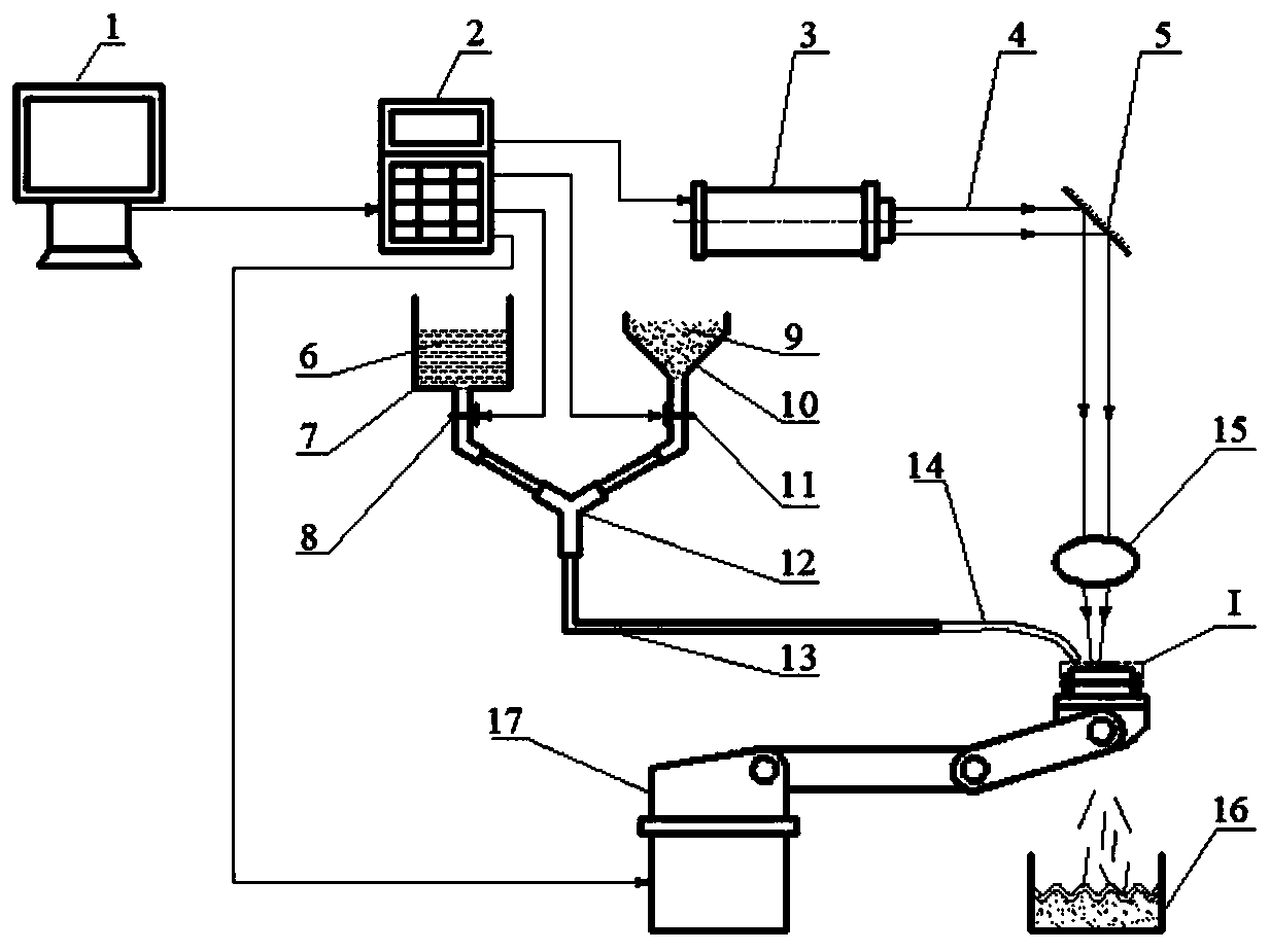
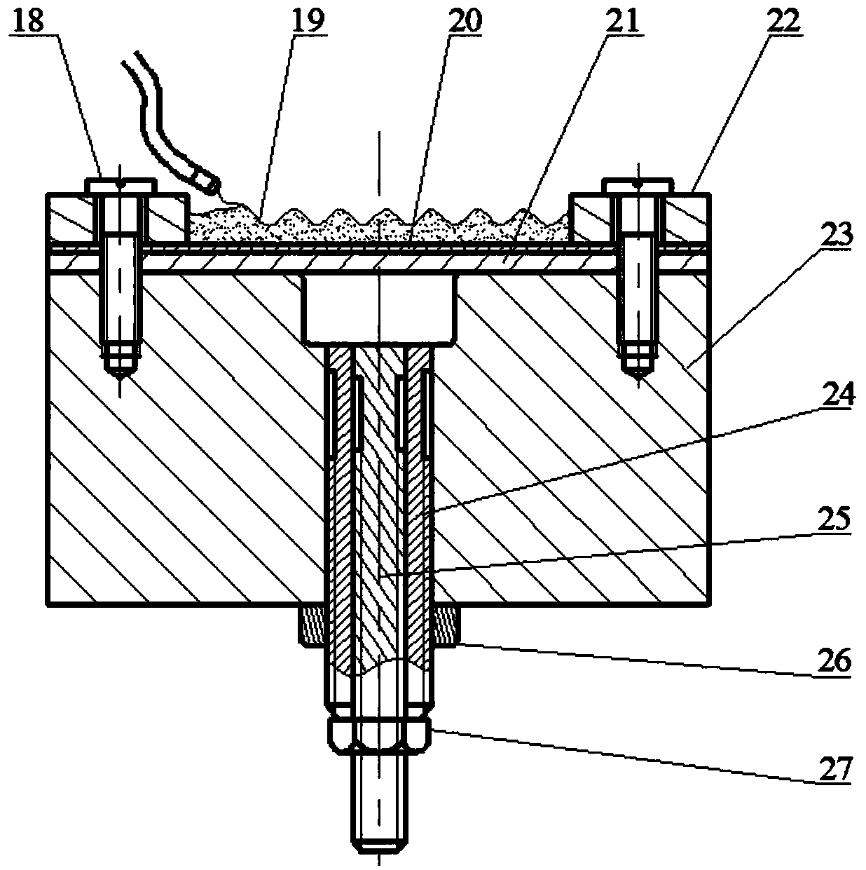
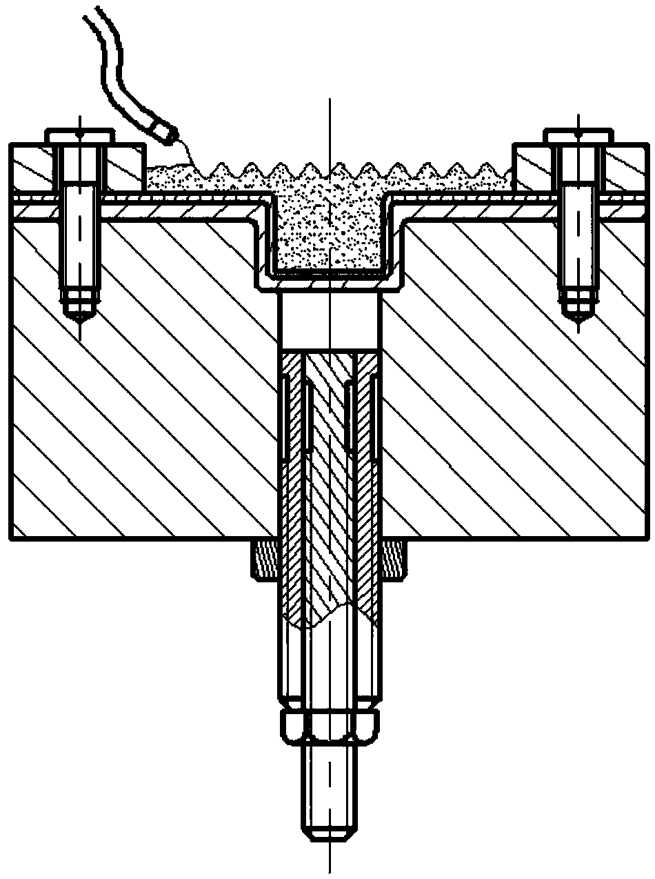
[0025] The device of the present invention includes a laser loading system, a mold forming system, a mixed liquid system and a control system; The pulsed laser beam 4 is generated by the laser 3, and the pulsed laser beam 4 is reflected by the total reflection mirror 5 during propagation, and after passing through the convex lens 15, it is irradiated on the suspended carbon particles 9 and the absorbing layer 20; the mold forming system Including die 23, metal sheet 21, absorption layer 20, constraining layer 19, blank holder 22, screw 18, large stud 24, small stud 25, large nut 26, small nut 27 and mechanical arm 17; die 23 Connect with the big stud 24 through threads, a small stud 25 is nested in the big stud 24, and the big stud 24 and the small stud 25 are connected through threads, a...


PUM


Abstract

The invention discloses a method and device for forming a stepped cylindrical member through laser impact, and belongs to the technical field of sheet metal forming. Nano-sized carbon particles are uniformly mixed with deionized water, then the mixture is sprayed on an absorption layer as a constraining layer, when a laser beam is irradiated to the suspended carbon particles and the absorption layer, an axial shock wave with direction of the acting force parallel to an optical axis is formed, while the suspended carbon particles absorb the laser energy, a lateral shock wave propagating to theperiphery is formed, so that a thin metal plate is plastically deformed, and the thin metal plate is bonded to an cavity of a concave mold. A combined die with adjustable depth is adopted, the pulsedlaser beam with small energy is adopted to impact the thin metal plate in multiple steps, and finally the complicated stepped cylindrical member with large forming depth and good forming quality is formed.

Description

Technical field: [0001] The invention belongs to the technical field of laser processing, and in particular relates to a method and a device for forming a step-shaped cylindrical part by laser shock. The invention is particularly suitable for forming parts with high precision and complex shapes. Background technique: [0002] With the development of modern industrial products in the direction of small batches, light weight, high strength, and high performance, it is difficult for traditional hydroforming methods to adapt to new development needs. For example, it is difficult to form high-strength, complex shapes using traditional hydraulic pressure. titanium alloy sheet metal parts. Laser shock forming technology is a new technology developed in recent years. It has the characteristics of strong flexibility, high forming precision, high forming efficiency and high repeatability. It is better adapted to the development direction of modern industrial products, especially suita...

Claims


Application Information

Patent Timeline
Patent Type & Authority Applications(China)
IPC IPC(8): B21D26/06B21D26/10
CPCB21D26/06B21D26/10
Inventor 张兴权余远超李民陈彬童靳于尹元德李胜祗
Owner ANHUI UNIVERSITY OF TECHNOLOGY
Why Eureka
Try Eureka