Milling machining device

A milling processing and equipment technology, applied in metal processing equipment, grinding/polishing equipment, grinding workpiece supports, etc., can solve the problems of difficult control of grinding amount and large labor input, and achieve the effect of reducing labor input

Active Publication Date: 2019-04-12
河南巨人起重机集团有限公司
View PDF7 Cites 3 Cited by
  • Summary
  • Abstract
  • Description
  • Claims
  • Application Information

AI Technical Summary

Problems solved by technology

[0004] The present invention intends to provide milling processing equipment to solve the problems of large manual input and difficulty

Method used


Image

  • Milling machining device
  • Milling machining device

Examples


Embodiment Construction

[0021] The following is further described in detail through specific implementation methods:

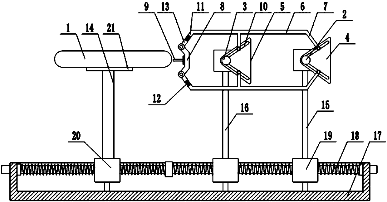
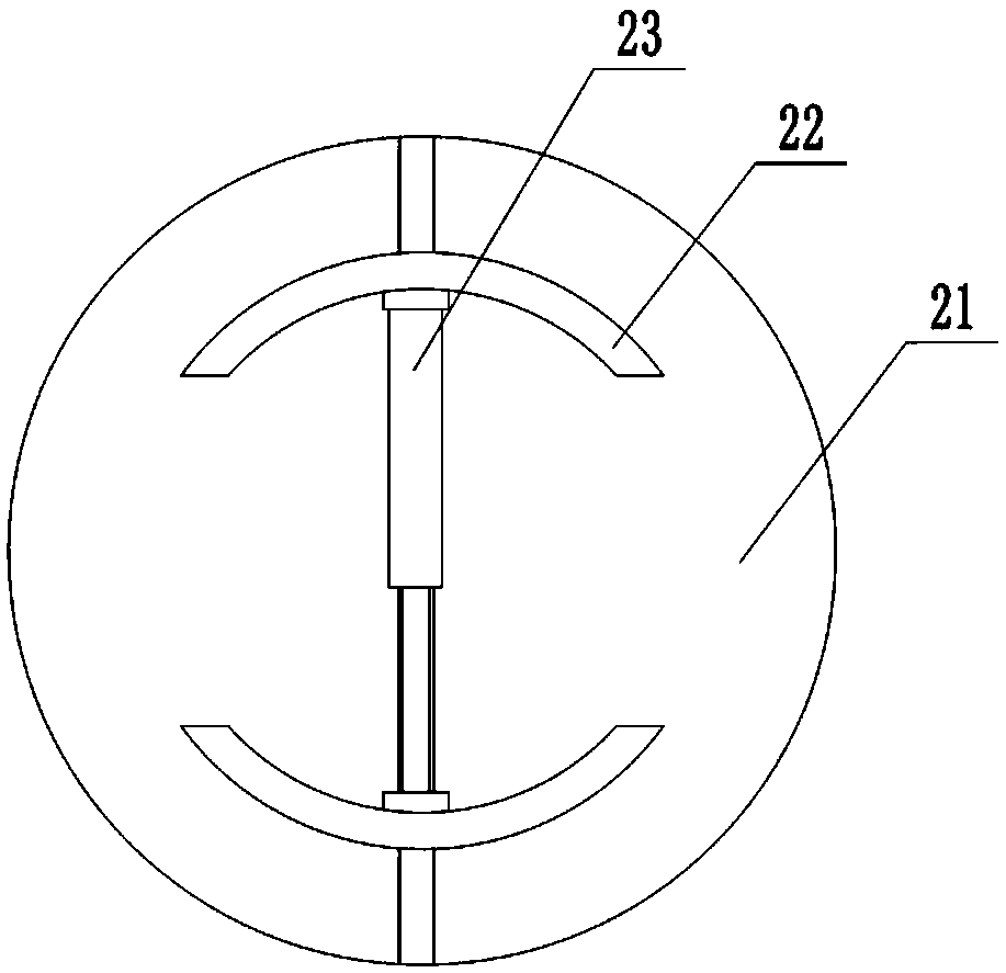
[0022] The reference signs in the drawings of the specification include: workpiece 1, first rotating shaft 2, second rotating shaft 3, first fixing seat 4, second fixing seat 5, bending rod 6, bending part 7, grinding seat 8, grinding Head 9, adjustment groove 10, first threaded cylinder 11, adjustment screw 12, second threaded cylinder 13, drive shaft 14, first pole 15, second pole 16, fixed groove 17, two-way screw rod 18, the first A nut 19, a second nut 20, a fixed plate 21, an arc block 22, and a telescopic rod 23.

[0023] The embodiment is basically as attached figure 1 Shown: milling processing equipment, comprise fixed groove 17, in the fixed groove 17 horizontal rotation is connected with two-way screw rod 18, the two ends of two-way screw rod 18 respectively pass through the left and right side walls of fixed groove 17, the two-way screw rod 18 The left end is coaxially ...


PUM


Abstract

The invention relates to the field of mechanical machining, and particularly discloses a milling machining device. The milling machining device comprises a fixing mechanism used for fixing a ring to be ground, the fixing mechanism can drive the ring to rotate, a grinding mechanism is arranged on one side of the fixing mechanism, and comprises a driving assembly and a grinding assembly, the drivingassembly comprises a first rotating shaft and a second rotating shaft, a synchronous belt is connected between the first rotating shaft and the second rotating shaft, a first fixed base and a secondfixed base are fixedly connected to the first rotating shaft and the second rotating shaft, two parallel bending rods are movably connected to the first fixed base, bending parts are arranged on the ends of the two bending rods, the two bending rods can form a rectangular structure, the middles of the two bending rods are movably connected to the second fixed base, and the grinding assembly is movably connected between the ends, away from the first fixed base, of the two bending rods. The problem that in the prior art, when the arc outer wall of a ring workpiece is ground, manual input is large, and the grinding amount is difficulty controlled is solved.

Description

technical field [0001] The invention relates to the field of mechanical processing, in particular to milling processing equipment. Background technique [0002] In the process of machining mechanical parts, circular workpieces are often processed. Since the shape of the ring workpiece is not as regular as that of the ordinary workpiece, the casting process is usually used for the processing of the ring workpiece, which makes there are a large number of gates on the arc surface of the circumference of the ring workpiece. affect the appearance of the product. Therefore, grinding is usually required after the casting of ring-like workpieces. [0003] In the prior art, the gate of the circular workpiece blank is manually polished. When grinding, the worker holds the workpiece and grinds off the residual gate on the grinder. However, manual grinding is difficult to control the grinding depth, and it is impossible to accurately control the grinding amount of the circular arc s...

Claims


Application Information

Patent Timeline
IPC IPC(8): B24B9/04B24B19/11B24B41/06B24B41/02B24B27/00
CPCB24B9/04B24B19/11B24B27/00B24B41/02B24B41/067
Inventor 王显峰
Owner 河南巨人起重机集团有限公司
Why Eureka
Try Eureka