Upper limb shoulder exoskeleton based on screw transmission structure

A wire transmission and exoskeleton technology, applied in manipulators, program-controlled manipulators, manufacturing tools, etc., can solve the problems of large motion deflection inertia, inoperability, worker fatigue, etc., to ensure motion performance, reduce structural thickness, and improve flexibility. Effect

Pending Publication Date: 2019-04-12
上海傲鲨智能科技有限公司
View PDF0 Cites 1 Cited by
  • Summary
  • Abstract
  • Description
  • Claims
  • Application Information

AI Technical Summary

Problems solved by technology

[0002] Many workers in the industrial environment need to use heavy tools to perform tasks every day. Long-term repetition and high-intensity exercise will cause a series of safety and efficiency problems such as worker fatigue and muscle damage. Therefore, an external force assist device is needed to help workers work
Existing devices generally use servo motors to directly drive the joints to complete the design of the exoskeleton. The motor and the reducer are directly combined and installed at the joints, resulting in the exoskeleton at the shoulder or elbow not being able to fit the user, and the thickness of the structure is relatively large. , the motion deflection inertia is very large, and the force following and boosting amplification cannot be well realized, which affects the motion performance of the exoskeleton. At the same time, the large structural parts increase the size of the user, making it impossible to operate in a small space, and unable to enter the conventional Buildings and industrial narrow environments, and the flexibility of the exoskeleton is poor, it is not easy for the user to operate, so a new type of device is needed to solve the existing problems

Method used


Image

  • Upper limb shoulder exoskeleton based on screw transmission structure
  • Upper limb shoulder exoskeleton based on screw transmission structure
  • Upper limb shoulder exoskeleton based on screw transmission structure

Examples


Embodiment Construction

[0027] The present invention will be further described below in conjunction with accompanying drawing:

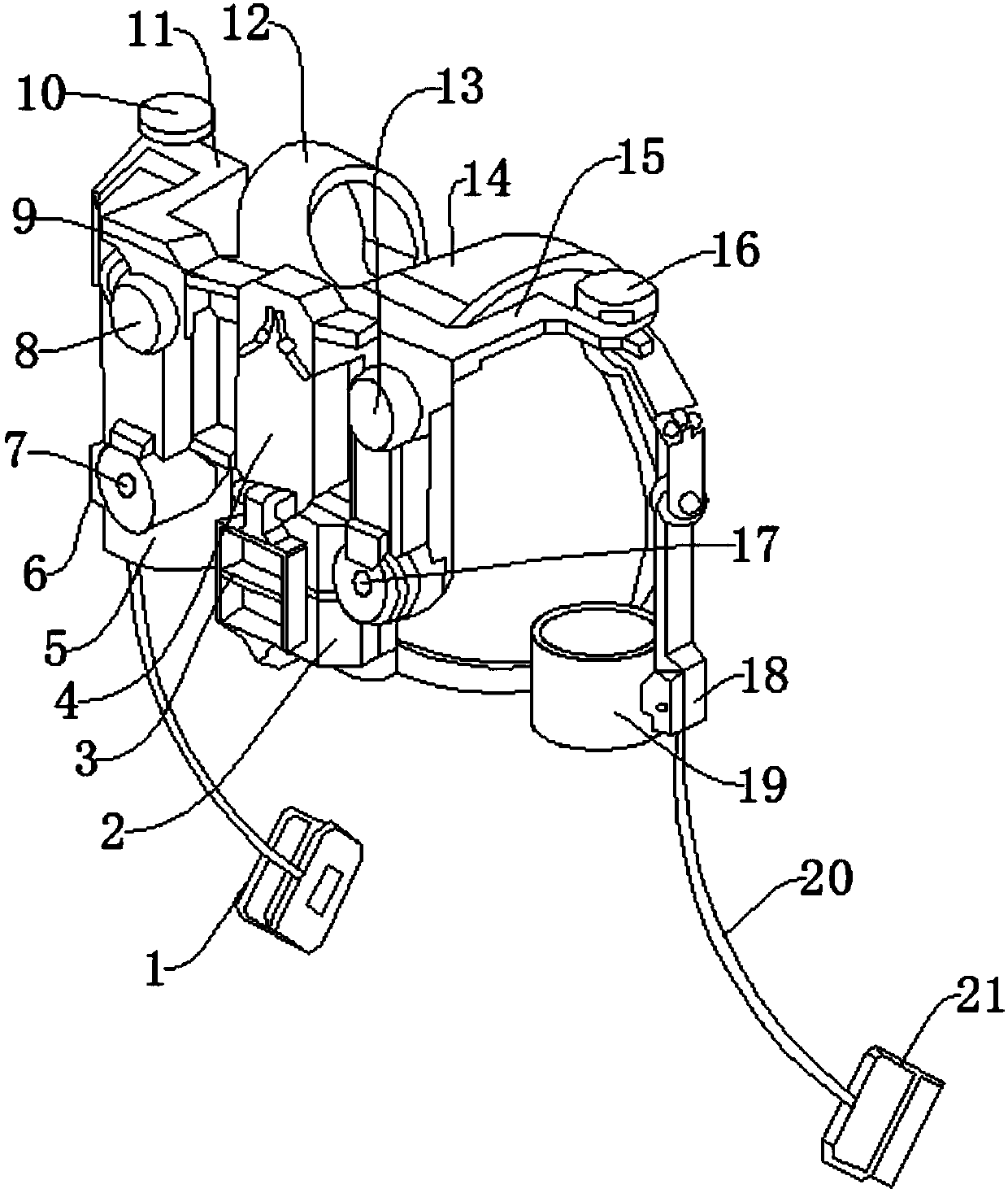
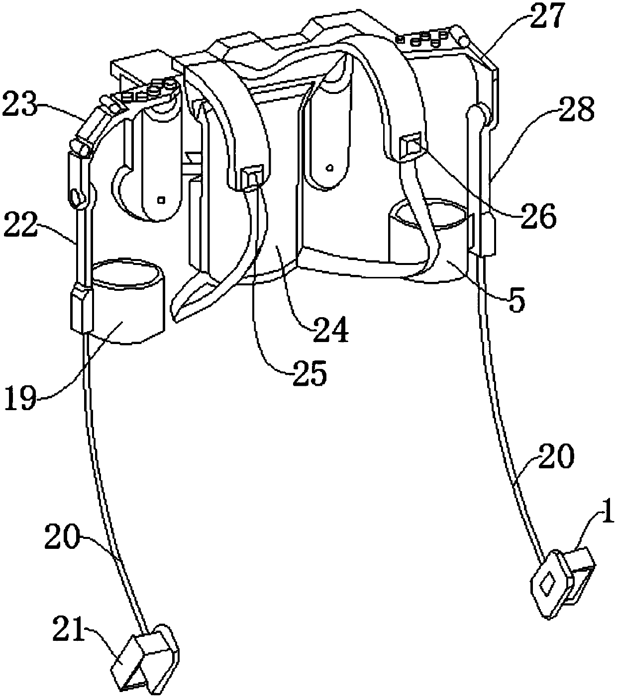
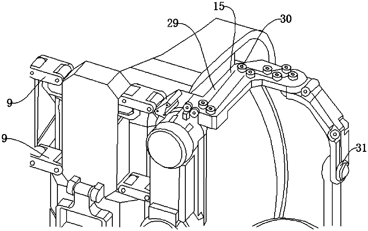
[0028] Such as Figure 1-Figure 5As shown, an upper limb shoulder exoskeleton based on a wire transmission structure includes a left hand effector 1, a cable 20 and a left upper arm force sensor 6, the upper side of the left hand effector 1 is provided with the cable 20, the cable 20 Information can be transmitted. The end of the cable 20 away from the left-hand effector 1 is provided with the left upper arm force sensor 6. The left upper arm force sensor 6 can measure the weight of the object being carried. The left upper arm force sensor 6 is provided with a left upper arm force sensor 6. The fixing ring 5, the left upper arm fixing ring 5 can fix the left upper arm, the upper side of the left upper arm fixing ring 5 is provided with a left upper arm steel member 28, and the upper side of the left upper arm steel member 28 is provided with a left steel wire steering membe...


PUM


Abstract

The invention discloses an upper limb shoulder exoskeleton based on a screw transmission structure. The upper limb shoulder exoskeleton comprises a left hand effect machine, a cable and a left upper arm force sensor, and has the beneficial effects that a steel wire, a left shoulder joint driver and a right shoulder joint driver are arranged to supply power, so that the condition that exoskeletonsof shoulders or elbows cannot be jointed to users, is avoided, the structure thickness is reduced, the movement deflection inertia is reduced, force following and assistance amplification can be wellrealized by the device, and the movement properties of the exoskeletons can be guaranteed. A locking nut, a radian hollow slot, a left shoulder tabula, a right shoulder tabula and a base are arranged,so that the width of the device can be adjusted according to the width of the shoulders of a wearer, the size of the users is reduced, and the wearers can be guaranteed to operate in a narrow space.A left upper arm steel member, a right upper arm steel member, a left steel wire steering structural member and a right steel wire steering structural member are arranged, so that the device has two driving freedom degrees, shoulder joints can extend outwards and contract inwards, and the flexibility of the device is greatly improved.

Description

technical field [0001] The invention relates to the fields of industrial automation, logistics handling, military use, civilian use, medical treatment and sports. The invention relates to an upper limb shoulder exoskeleton based on a wire transmission structure. Background technique [0002] Many workers in the industrial environment need to use heavy tools to perform tasks every day. Long-term repetition and high-intensity exercise will cause a series of safety and efficiency problems such as worker fatigue and muscle damage. Therefore, an external force assist device is needed to help workers work. Existing devices generally use servo motors to directly drive the joints to complete the design of the exoskeleton. The motor and the reducer are directly combined and installed at the joints, resulting in the exoskeleton at the shoulder or elbow not being able to fit the user, and the thickness of the structure is relatively large. , the motion deflection inertia is very large,...

Claims


Application Information

Patent Timeline
Patent Type & Authority Applications(China)
IPC IPC(8): B25J9/00B25J9/10
CPCB25J9/0006B25J9/104
Inventor 徐振华
Owner 上海傲鲨智能科技有限公司
Why Eureka
Try Eureka