Eureka AIR delivers breakthrough ideas for toughest innovation challenges, trusted by R&D personnel around the world.

Garbage can with compaction function for green building

A technology of green building and trash can, applied in the direction of trash can, garbage collection, application, etc., can solve the problems of simple structure, occupying space and inconvenient use of trash can, and achieve the effect of novel design

Inactive Publication Date: 2019-04-12
任国斌
View PDF5 Cites 1 Cited by
  • Summary
  • Abstract
  • Description
  • Claims
  • Application Information

AI Technical Summary

Problems solved by technology

[0003] The structure of the garbage can in the community is simple now, and it is only a single container. Due to the different shapes of different garbage, it takes up a lot of space when it is disposed.

Method used


Image

  • Garbage can with compaction function for green building
  • Garbage can with compaction function for green building
  • Garbage can with compaction function for green building

Examples


Embodiment 1

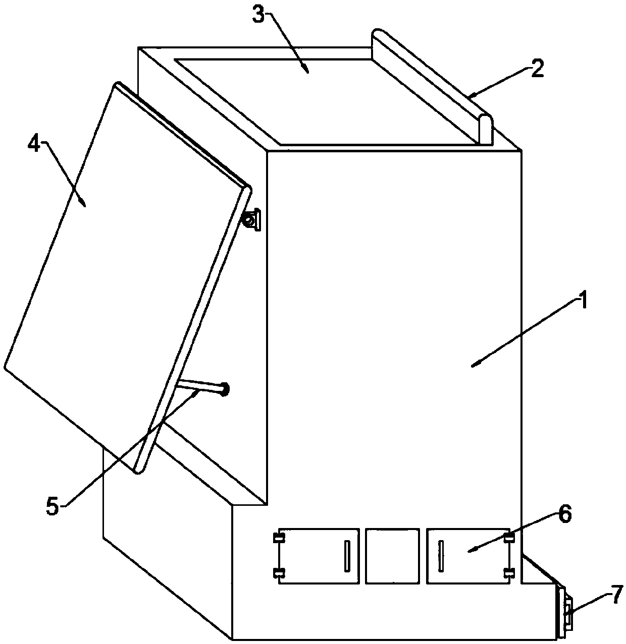
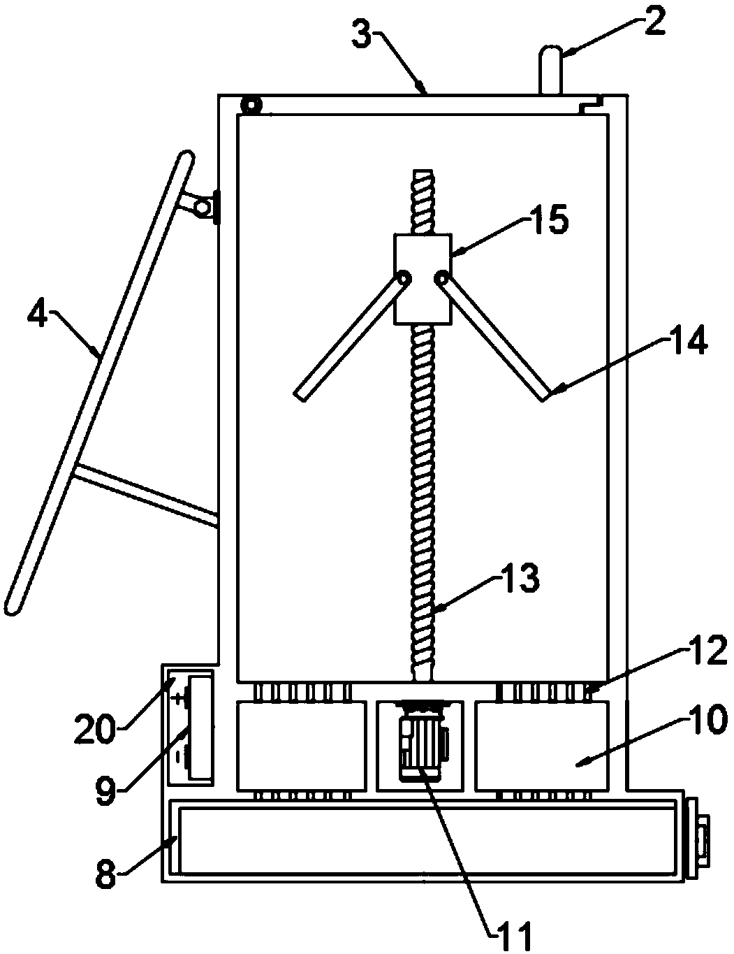
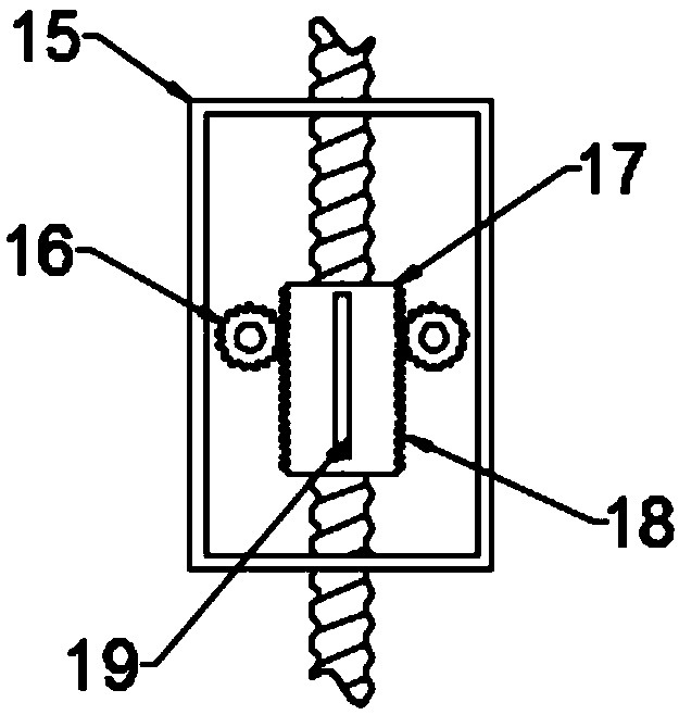
[0022] In the embodiment of the present invention, a garbage can with a compacting function for green buildings includes a garbage can body 1; 7, the collection tank placement cavity 8, and the collection tank placement cavity 8 communicates with the inside of the garbage can body 1 through the drain hole 12, and the sewage inside the garbage can body 1 enters the waste water collection tank 7 through the drainage hole 12 to collect, so The upper end of the trash can body 1 is hinged with an upper cover 3, and the upper cover 3 is fixed with a pull handle 2, so as to facilitate the opening of the upper cover 3. The inside of the trash can body 1 is provided with a motor 11, the motor 11 The output shaft is fixedly connected with the threaded rod 13 through a coupling, and the threaded rod 13 is sleeved with a transmission block 15. The inside of the transmission block 15 is a cavity structure, and the inner side of the transmission block 15 is slidingly connected with a threade...

Embodiment 2

[0028] The difference between the second embodiment and the first embodiment is that the side end of the garbage can body 1 is obliquely installed with a solar panel 4 through the support rod 5, and the solar panel 4 is electrically connected with the battery 9 placed in the battery storage cavity 20, and is connected by The solar panel 4 charges the storage battery 9 to save energy.

[0029] It should be noted that the motor in this application is an application of the prior art. The motor drives the threaded rod to rotate. When the threaded rod rotates, it drives the threaded sleeve to move. When the threaded sleeve moves downward, it will drive the pressure plate to rotate upward. When the pressure plate moves to In the horizontal state, the threaded sleeve no longer moves relative to the transmission block. At this time, it will drive the transmission block and the pressure plate to move downwards to realize the compaction of garbage. When the threaded sleeve moves upwards,...


PUM


Abstract

The invention discloses a garbage can with a compaction function for a green building. The garbage can comprises a garbage can body; a collecting groove storing cavity used for storing a waste water collecting groove is formed in the lower end of the garbage can body, the collecting groove storing cavity communicates with the inner side of the garbage can body through a drain hole, a motor is arranged on the inner side of the garbage can body, an output shaft of the motor is fixedly connected with a threaded rod through a coupling, a transmission block sleeves the threaded rod, the interior ofthe transmission block is of a cavity structure, the inner side of the transmission block is slidably connected with a threaded sleeve, the threaded sleeve is in threaded connection with the threadedrod, gears are symmetrically arranged at the two ends of the threaded sleeve, the gears mesh with strip-shaped teeth on the threaded sleeve, and rotating shafts at the two ends of the gears penetratethrough the transmission block to be fixedly connected with a pressing plate. The garbage can is novel in design, and the problems that an existing garbage can is simple in structure, does not have the compaction function and is small in storage volume are effectively solved.

Description

technical field [0001] The invention relates to the technical field of green buildings, in particular to a garbage bin with a compacting function for green buildings. Background technique [0002] Green building refers to the maximum saving of resources in the whole life cycle of the building, including energy saving, land saving, water saving, material saving, etc., to protect the environment and reduce pollution, to provide people with healthy, comfortable and efficient use of space, and to be in harmony with nature. Buildings that live in harmony. Green building technology focuses on low consumption, high efficiency, economy, environmental protection, integration and optimization. It is a benefit sharing between man and nature, present and future, and a means of sustainable development. [0003] The structure of the garbage can in the community is simple now, and it is only a single container. Due to the different shapes of different garbage, it takes up a lot of space w...

Claims


Application Information

Patent Timeline
Patent Type & Authority Applications(China)
IPC IPC(8): B65F1/14
CPCB65F1/14B65F1/1405B65F2210/162B65F2210/172
Inventor 任国斌
Owner 任国斌
Why Eureka
Eureka Blog
Learn More