A domestic waste disposal device

A treatment device and domestic waste technology, applied in the direction of grain treatment, transportation and packaging, manufacturing tools, etc., can solve the problem of no compaction treatment, etc., and achieve the effect of easy transshipment treatment

Active Publication Date: 2022-04-15
池州市芯村里新材料科技有限公司
View PDF7 Cites 0 Cited by
  • Summary
  • Abstract
  • Description
  • Claims
  • Application Information

AI Technical Summary

Problems solved by technology

[0009] The object of the present invention is to provide a domestic waste disposal device to solve the problem that the traditional waste disposal device does not have compaction treatment in the above-mentioned background technology

Method used


Image

  • A domestic waste disposal device
  • A domestic waste disposal device
  • A domestic waste disposal device

Examples


Embodiment 1

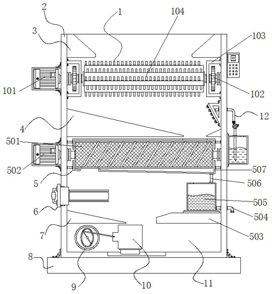
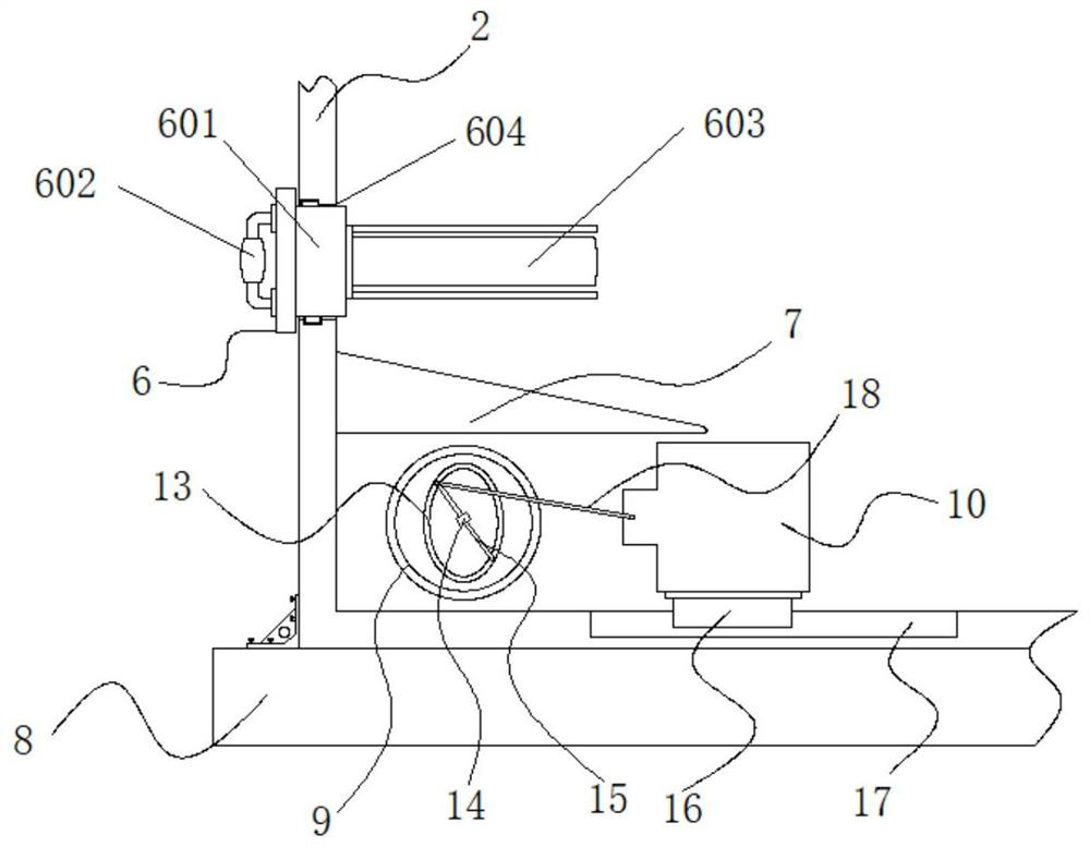
[0035] Example 1: See Figure 1-6 , a domestic waste treatment device, comprising a base 8, the top of the base 8 is fixedly connected with a frame body 2, the top inside the frame body 2 is provided with a first material guide block 3, and the top ends of the inside of the frame body 2 are provided with There is a crushing mechanism 1, a second material guide block 4 is arranged inside the bottom frame body 2 of the crushing mechanism 1, and a dehydration mechanism 5 is arranged at the middle position inside the bottom frame body 2 of the second material guide block 4, and the outer side of the frame body 2 A spray mechanism 12 is provided at the middle position of the dehydration mechanism 5, and a magnetic structure 6 is provided on one side inside the bottom frame body 2 of the dehydration mechanism 6. A third material guide block 7 is arranged inside the bottom frame body 2 of the magnetic structure 6, and a third material guide block 7 is arranged inside the frame body 2. ...

Embodiment 2

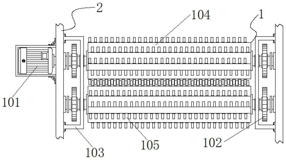
[0038] Embodiment 2: The crushing mechanism 1 is composed of a first driving motor 101, a gear 102, a cover 103, a first crushing roller 104 and a second crushing roller 105. The model of the first driving motor 101 can be Y90L-2, the first The crushing roller 104 is arranged on the top inside the frame body 2, and the two ends of the first crushing roller 104 are fixedly connected with the top ends on both sides inside the frame body 2, and one end of the first crushing roller 104 is provided with a second crushing roller 105, and the first crushing roller 104 Both ends of the roller 104 and the second crushing roller 105 are provided with a gear 102, the outside of the gear 102 is provided with a cover 103, one side of the cover 103 is fixedly connected with the frame body 2, and the first drive motor 101 is arranged on the frame body 2 At the top of the outer side, the first drive motor 101 is fixedly connected to one end of the first crushing roller 104 through a coupling, ...

Embodiment 3

[0040] Embodiment 3: The dehydration mechanism 5 is composed of a drum 501, a second drive motor 502, a support seat 503, an outlet pipe 504, a collection box 505, a first conduit 506 and an outer cylinder 507. The model of the second drive motor 502 can be Y90S -2, the second drive motor 502 is arranged at the middle position on the outer side of the frame body 2, the roller 501 is arranged at the middle position inside the frame body 2, and the output end of the roller 501 is connected to the second drive motor 502 through a coupling One end is fixedly connected, and an outer cylinder 507 is arranged on the outside of the drum 501, and both sides of the outer cylinder 507 are fixedly connected to the middle positions of both sides inside the frame body 2, and the support seat 503 is fixedly connected to the bottom end of one side inside the frame body 2 A collection box 505 is fixedly connected to the top of the support base 503, a water outlet pipe 504 is fixedly connected t...


PUM


Abstract

The invention discloses a domestic waste treatment device, specifically relates to the technical field of domestic waste treatment devices, comprising a base, the top of the base is fixedly connected with a frame, and the top inside of the frame is provided with a first guide material The top of both sides inside the frame is provided with a crushing mechanism, the inside of the bottom frame of the crushing mechanism is provided with a second material guide block, and the middle position inside the bottom frame of the second material guide block is provided with a dehydration mechanism. In the present invention, a compression mechanism is arranged at the bottom end inside the frame body, and the controller controls the operation of the third drive motor. The third drive motor drives the rotary block through the coupling, and the rotary block rotates through the first movable rod and the second movable rod. Drive the compression block to reciprocate, the slider and the chute guide the movement of the compression block, the garbage passing through the bar magnet falls to the top of the third material guide block and slides into the compression cavity, the compression block compresses the garbage Reduces the volume of litter particles.

Description

technical field [0001] The invention relates to the technical field of domestic waste treatment devices, in particular to a domestic waste treatment device. Background technique [0002] With the development of urban construction and the improvement of people's quality of life, more and more domestic waste is produced, which not only affects people's health, but also affects the cleanliness of the surrounding environment. The produced domestic waste contains solid, Liquid and some metal garbage, among them, liquid garbage is easy to breed bacteria, which will cause the garbage to rot faster and cause bacteria to grow too fast. Solid garbage can be recycled and reused to improve the utilization rate of metal resources. [0003] In the process of realizing the present invention, the inventors have found that at least the following problems in the prior art have not been resolved: [0004] (1) The traditional garbage disposal device does not have compaction treatment, and it i...

Claims


Application Information

Patent Timeline
Patent Type & Authority Patents(China)
IPC IPC(8): B09B3/00B09B5/00B02C18/14A61L2/18A61L11/00B03C1/26B30B9/00
CPCB09B3/00B09B5/00B02C18/0092B02C18/142A61L2/18A61L11/00B03C1/26B30B9/00B02C2201/06B09B2101/02
Inventor 李彩微
Owner 池州市芯村里新材料科技有限公司
Why Eureka
Try Eureka