High-accuracy intelligent feeding tool

A high-precision, intelligent technology, applied in the direction of conveyor objects, transportation and packaging, furnaces, etc., can solve the problems of fragile lenses, inconvenient adjustment, low clamping precision, etc., and achieve the effect of strong protection and guaranteed clamping precision

Inactive Publication Date: 2019-04-12
武汉安比克科技有限公司
View PDF14 Cites 3 Cited by
  • Summary
  • Abstract
  • Description
  • Claims
  • Application Information

AI Technical Summary

Problems solved by technology

[0003] At present, when the existing optical lens feeding tool is clamping the optical lens, on the one hand, during the clamping process, the rigid connection

Method used


Image

  • High-accuracy intelligent feeding tool
  • High-accuracy intelligent feeding tool
  • High-accuracy intelligent feeding tool

Examples


Embodiment 1

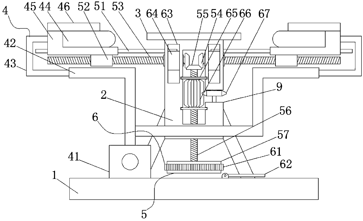
[0038] Such as figure 1As shown, a high-precision intelligent feeding tool provided in Embodiment 1 includes a base plate 1 and a support column 2 fixedly installed on the upper end surface of the base plate 1. Specifically, four support beams are fixedly installed around the outer surface of the support column 2 , and the bottom end of the support beam is fixedly installed on the upper end surface of the base plate 1 to support the support column 2. The upper end surface of the support column 2 is fixedly installed with a support platform 3, and the right side of the support platform 3 is provided with a window 9. include:

[0039] Four clamping mechanisms 4 are symmetrically distributed around the support column 2 and are used to clamp materials from four directions; the clamping mechanism 4 includes an air pump 41, a sleeve 42, an air intake pipe 43, and an arc-shaped air bag 44. The lower backing plate 45 and the upper backing plate 46, the air pump 41 is fixedly installe...

Embodiment 2

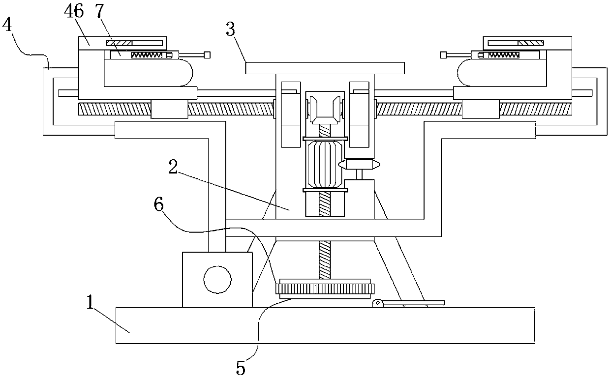
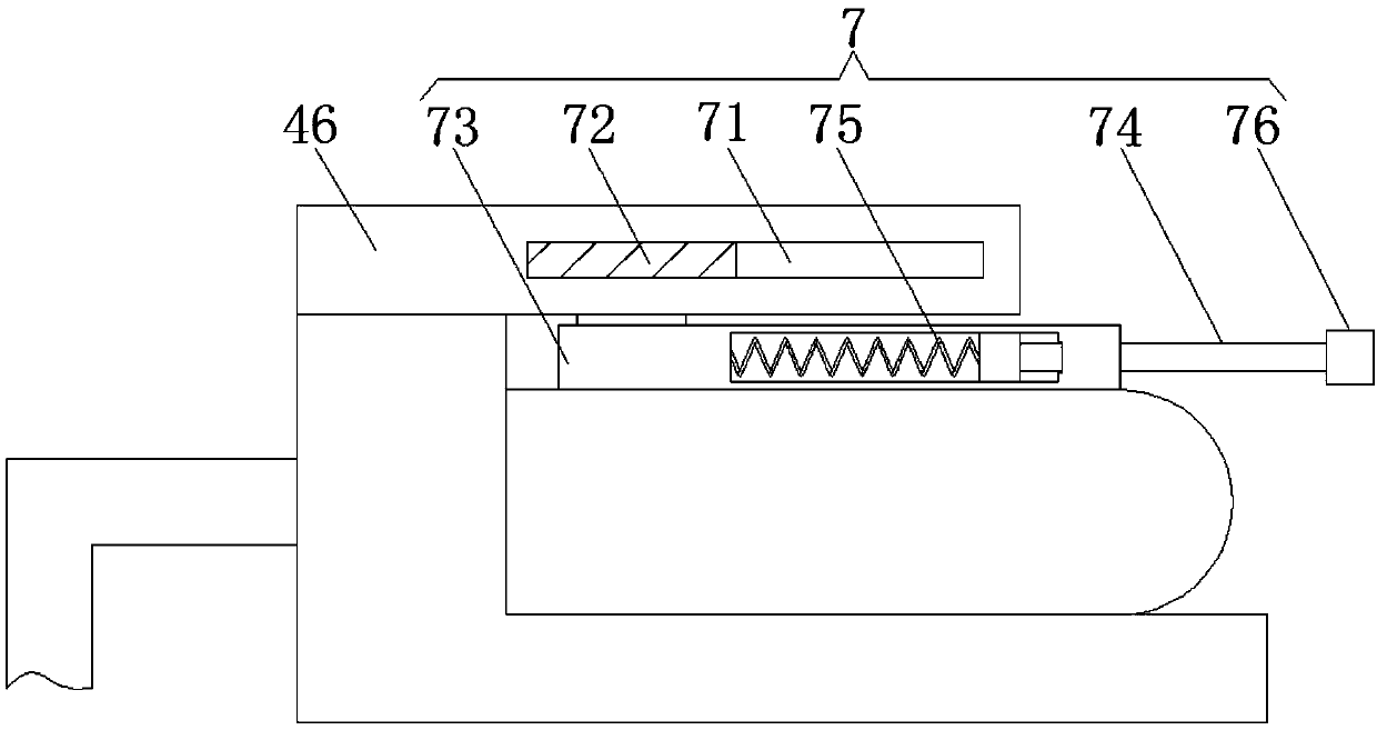
[0047] Such as Figure 2-3 As shown, the difference between this embodiment and the first embodiment is that: it also includes a pre-positioning component 7, which is arranged inside the clamping mechanism 4;

[0048] Pre-positioning assembly 7 comprises transverse chute 71, slide plate 72, baffle plate 73, telescoping rod 74, spring 75 and top block 76, and transverse chute 71 is offered at the bottom of upper backing plate 46, and slide plate 72 is arranged on the bottom of transverse chute 71. Inner cavity, the lower end surface of the slide plate 72 extends to the bottom of the upper backing plate 46, and the slide plate 72 can slide in the inner cavity of the transverse chute 71, and one end of the top of the baffle plate 73 is fixedly installed on the lower end surface of the slide plate 72, and the baffle plate 73 The lower end surface of the arc-shaped airbag 44 is fixedly connected to the upper end surface of the arc-shaped airbag 44. Specifically, during the expansio...

Embodiment 3

[0051] Such as Figure 4 As shown, the difference between this embodiment and the above-mentioned embodiments is that it also includes a storage slot 8, and a stopper is provided near one end of the support table 3, and the size of the storage slot 8 is larger than the size of the top block 76, when the clamping mechanism 4 After moving a certain distance, the airbag contacts the optical lens, and the top block 76 will enter the storage groove 8, and the contact part between the arc-shaped airbag 44 and the optical lens will expand upwards, and the expanded part will extend to between the top block 76 and the optical lens. Block 76 does not come into contact with the optical lens, further enhancing the effect of flexible clamping.


PUM


Abstract

The invention relates to the technical field of optical lens polishing tool equipment, and discloses a high-accuracy intelligent feeding tool. The high-accuracy intelligent feeding tool comprises a base plate and a supporting column, wherein the supporting column is fixedly installed on the upper end face of the base plate. A supporting platform is fixedly installed on the upper end face of the supporting column, and a window is formed in the right side face of the supporting platform. The high-accuracy intelligent feeding tool further comprises four clamping mechanisms, a horizontal movementmechanism and a vertical movement mechanism. The four clamping mechanisms are arranged on the periphery of the supporting column in a central symmetry distribution mode and used for clamping materialsin the four directions. The horizontal movement mechanism is arranged on the lower end faces of the clamping mechanisms, installed on the supporting column, and used for moving the clamping mechanisms in the horizontal direction and adjusting the clamping force. The vertical movement mechanism is arranged inside the supporting column, and used for adjusting the clamping mechanisms in the verticaldirection and adjusting the clamping height. By the adoption of the high-accuracy intelligent feeding tool, the clamping position can be adjusted according to the size and the thickness of an opticallens, and the clamping accuracy is improved. In addition, flexible clamping operation can be utilized to replace rigid clamping operation, and the lens is better protected.

Description

technical field [0001] The invention relates to the technical field of optical lens grinding tooling equipment, in particular to a high-precision intelligent feeding tooling. Background technique [0002] The flatness and uniformity of the surface of the optical lens will directly affect the use effect of the optical lens. Therefore, during the processing of the optical lens, the surface needs to be polished with high precision. During the grinding process, the feeding mechanism of the optical lens Among them, the clamping effect of the tooling will directly affect the polishing effect of the optical lens. [0003] At present, when the existing optical lens feeding tool is clamping the optical lens, on the one hand, during the clamping process, the rigid connection between the clamping mechanism and the optical lens is easy to damage the lens; And the thickness is adjusted to the clamping position, and the clamping accuracy is low. Contents of the invention [0004] (1) ...

Claims


Application Information

Patent Timeline
IPC IPC(8): B65G49/06
CPCB65G49/061
Inventor 陈才安
Owner 武汉安比克科技有限公司
Why Eureka
Try Eureka