Overturning and suspension device for projectile body vertical mode test and use method thereof

A modal test, suspension device technology, applied in the directions of transportation and packaging, load suspension components, etc., can solve the problems of non-compliance with safe operation regulations, high risks, and high cost of motor mechanism turnover, and achieve stable and controllable turnover process. The effect of low cost, high reliability and safety

Active Publication Date: 2019-04-12
THE GENERAL DESIGNING INST OF HUBEI SPACE TECH ACAD
View PDF8 Cites 3 Cited by
  • Summary
  • Abstract
  • Description
  • Claims
  • Application Information

AI Technical Summary

Problems solved by technology

The flipping with double carriages is suitable for projectiles with small mass and size. For the flipping of large-sized and high-mass projectiles, due to the "crooked pull and inclined hanging" in the flipping, it does not meet the safety operation regulations and is risky; the hydraulic mechanism The cost of turning over and turning over the motor mechanism is too high. After the projectile is turned over, it is necessary to lift the upper part of the projectile to the pallet of the modal test tower. The projectile bears tension during the lifting process. Be applicable

Method used


Image

  • Overturning and suspension device for projectile body vertical mode test and use method thereof
  • Overturning and suspension device for projectile body vertical mode test and use method thereof
  • Overturning and suspension device for projectile body vertical mode test and use method thereof

Examples


Embodiment Construction

[0035] Embodiments of the present invention will be described in further detail below in conjunction with the accompanying drawings.

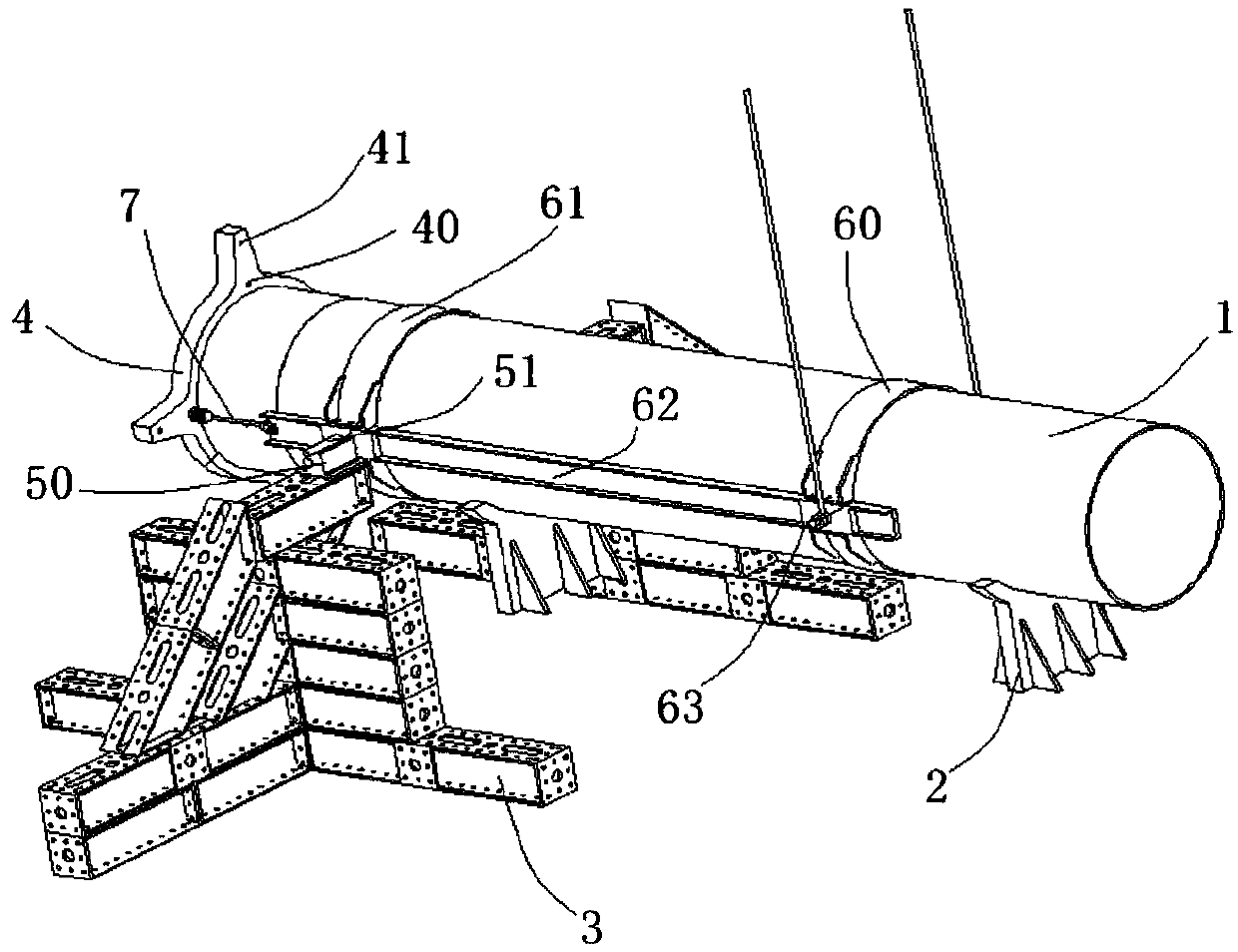
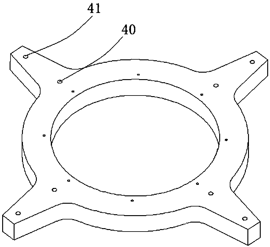
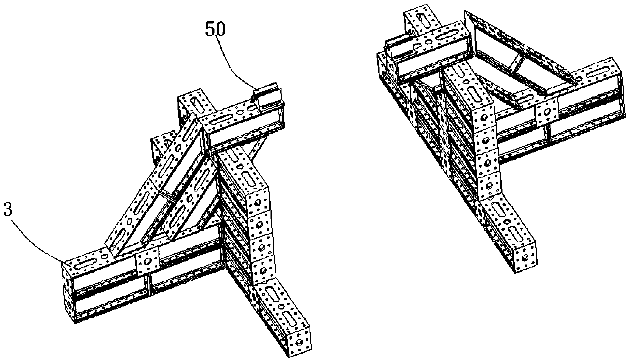
[0036] see figure 1 As shown, the embodiment of the present invention provides a flip suspension device for the vertical modal test of the projectile, including a bracket 2, two support platforms 3, a rotating assembly and a suspension 4, and the bracket 2 is used to support the projectile 1. Increase or decrease the number according to the actual situation. The two support platforms 3 are used to provide a rotating support platform for the projectile 1. In actual use, they are symmetrically arranged on both sides of the projectile 1. The rotating assembly includes a fixed piece and a symmetrical Rotating parts arranged on both sides of the fixing part, one end of the rotating part is connected with the fixing part, and the other end is fixed on the supporting platform 3, the fixing part is used to be set on the elastic body 1, when the fixing ...


PUM


Abstract

The invention discloses an overturning and suspension device for a projectile body vertical mode test and a use method of the overturning and suspension device for the projectile body vertical mode test. The overturning and suspension device for the projectile body vertical mode test comprises a bearing frame, two supporting platforms, a rotating assembly and a suspension piece. The bearing frameis used for supporting the projectile body. The two supporting platforms are used for providing rotation supporting platforms for the projectile body. The rotating assembly comprises a fixing piece and rotating pieces which are symmetrically arranged on the two sides of the fixing piece. One end of each rotating piece is connected with the corresponding fixing piece, and the other end of each rotating piece is fixed to the corresponding supporting platform. Each fixing piece is used for arranging on the projectile body in a sleeving manner. When the fixing pieces are lifted, the fixing piecesdrive the projectile body to rotate around the rotating pieces within a preset angle range. The suspension device is arranged at one end of the projectile body and used for assisting the projectile body in suspension. The invention also provides a use method of the overturning and suspension device for the projectile body vertical mode test. The overturning and suspension device for the projectilebody vertical mode test is suitable for overturning and vertical suspension of the projectile body which has large mass, cannot bear pull and bend and can only bear pressure, and the overturning andsuspension device for the projectile body vertical mode test has the features of being simple in structure, low in cost and safe.

Description

technical field [0001] The invention relates to the technical field of large-scale spacecraft mechanical environment tests, in particular to an overturning suspension device and a use method for vertical modal tests of projectile bodies. Background technique [0002] The boundary conditions in the modal test have a great influence on the accuracy of the modal parameters. In order to obtain the modal parameters of the free state of the projectile, the boundary conditions should be as close as possible to the free state. The commonly used modal test suspension schemes mainly include horizontal suspension and vertical suspension. Under the joint action, large bending will be generated, which will affect the connection stiffness, resulting in a large difference between the modal test results and the free state under certain working conditions. The modal test was carried out by means of dynamic suspension. [0003] When a large projectile is subjected to a vertical suspension m...

Claims


Application Information

Patent Timeline
IPC IPC(8): B66C13/08
CPCB66C13/08
Inventor 马征李东强刘凯付密果向志坚温涛冯南鹏赵全曹鹏王坤
Owner THE GENERAL DESIGNING INST OF HUBEI SPACE TECH ACAD
Why Eureka
Try Eureka