
Energy harvesting type speed reducing mechanism

A deceleration mechanism and collection type technology, applied in electromechanical devices, controlling mechanical energy, roads, etc., to achieve the effects of high reliability, simple structure, and improved power generation efficiency

Pending Publication Date: 2019-04-12
SOUTHWEST JIAOTONG UNIV
View PDF9 Cites 2 Cited by
  • Summary
  • Abstract
  • Description
  • Claims
  • Application Information

AI Technical Summary

Problems solved by technology

[0006] The purpose of the present invention is to provide an energy collection type deceleration mechanism, which can effectively solve the technical problem of collecting mechanical energy when the automobile passes through the deceleration belt

Method used


Image

  • Energy harvesting type speed reducing mechanism
  • Energy harvesting type speed reducing mechanism
  • Energy harvesting type speed reducing mechanism

Examples


Embodiment Construction

[0027] The present invention will be further described in detail below in conjunction with the accompanying drawings and specific embodiments.

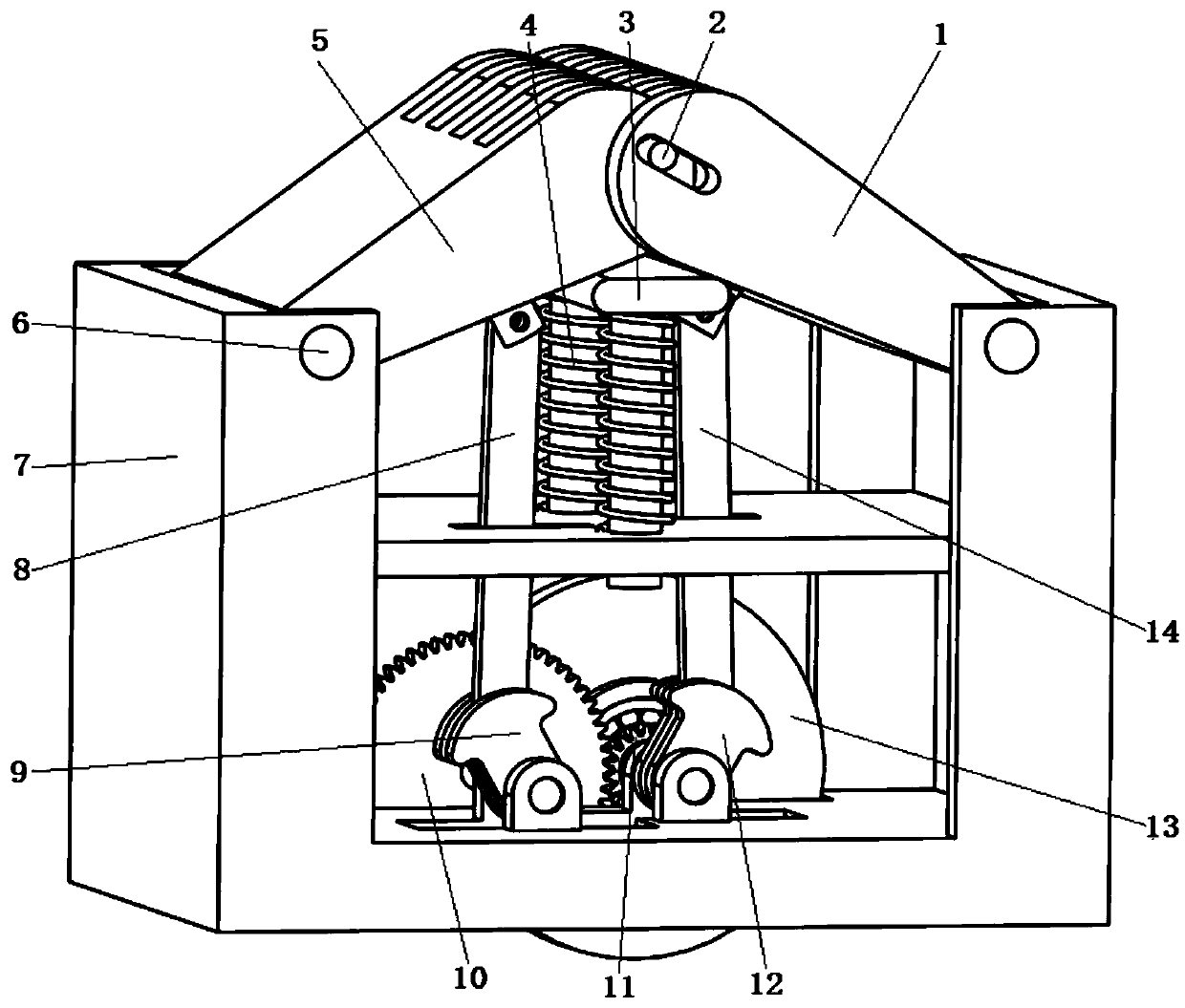
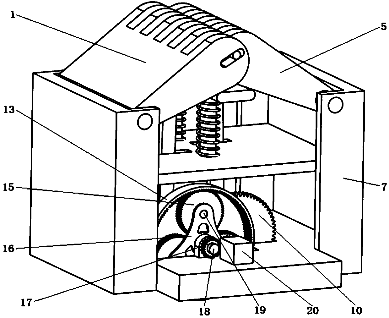
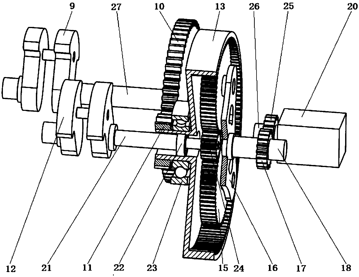
[0028] The energy harvesting speed reduction mechanism is provided with a speed coupling device, which includes a speed reduction belt part, a motion conversion part and a speed coupling part. The deceleration belt part includes two front passing surfaces 1 that are embedded in each other's tooth gaps and pinned by bolts, which can swing around the fixed shaft 6, the reverse passing surface 5, and the bolt 2 that connects the comb teeth. Sliding in the elongated latch hole of front and back crossing the vehicle surface, there is a horizontal plate 3 that provides the damping force and reset force of the speed bump below the speed bump, and there is a return spring 4 between the cross plate 3 and the middle plate of the chassis 7. The motion conversion part can convert up and down motion into continuous rotary motion. It is composed of...


PUM


Abstract

The invention provides an energy harvesting type speed reducing mechanism, and relates to the technical field of power generation of deceleration strips. Comb tooth ends are arranged on a front vehicle passing surface and a reverse vehicle passing surface of a deceleration strip, are inserted in each other's tooth gaps, and are in pin connection with each other by a latch, and the other ends of the front vehicle passing surface and the reverse vehicle passing surface are separately fixed to the upper portion of a case; a transverse plate is arranged on the lower portion of the deceleration strip, a spring guide rod and a reset spring are arranged on the bottom of the transverse plate, one end of a front connecting rod is hinged to the lower portion of the front vehicle passing surface through a cylindrical pin while the other end is hinged to a front bent axle; one end of a rear connecting rod is hinged to the lower portion of the reverse vehicle passing surface through a cylindrical pin while the other end is hinged to a rear bent axle; a first shaft is fixed to a first gear wheel engaged with a first pinion, the first pinion is fixed to a gear ring of a differential gear train, asecond shaft of the front bent axle penetrates through the first pinion and the gear ring and is fixed to a sun gear of the differential gear train, an output shaft of a planet carrier is fixed to asecond gear wheel engaged with a second pinion, and the second pinion is fixed to an input shaft of a generator.

Description

technical field [0001] The invention relates to the technical field of speed bump power generation. Background technique [0002] With the development of urban transportation and the continuous improvement of road infrastructure, the power consumption of road facilities is gradually increasing, which will inevitably increase the power load of cities. At the same time, in some remote areas, due to the lack of corresponding stable power supply capabilities, The lack of infrastructure increases the probability of traffic accidents. In order to solve these problems, road energy harvesting technology has been extensively studied, hoping to recycle the energy existing in the environment to supply power for road infrastructure, such as using solar energy, wind energy and mechanical energy, among which mechanical energy is less affected by environmental factors , and the advantages of widespread existence have been extensively studied. The energy harvesting speed bump is a kind of...

Claims


Application Information

Patent Timeline
Patent Type & Authority Applications(China)
IPC IPC(8): E01F9/529H02K7/18
CPCH02K7/1861E01F9/529
Inventor 张祖涛王伟袁艳平郭亮李海韩磊潘亚嘉
Owner SOUTHWEST JIAOTONG UNIV
Learn More