Shear wall connection structure and construction process thereof

A technology for connecting structures and construction techniques, applied in the direction of structural elements, walls, building components, etc., can solve the problems of rough end walls, poor connection effect, and small contact area of ​​shear walls.

Inactive Publication Date: 2019-04-12
南通市建筑设计研究院有限公司
View PDF6 Cites 15 Cited by
  • Summary
  • Abstract
  • Description
  • Claims
  • Application Information

AI Technical Summary

Problems solved by technology

[0004] However, because the end wall of the shear wall is relatively rough, there is a gap between the lower end wall of the upper wall 1 and the upper end wall of the lower wall 2, and the actual contact area between the upper wall 1 and the lower wall 2 is small, As a result, the actual connection effect between the upper wall 1 and the lower wall 2 is poor, so it needs to be improved

Method used


Image

  • Shear wall connection structure and construction process thereof
  • Shear wall connection structure and construction process thereof
  • Shear wall connection structure and construction process thereof

Examples


Embodiment

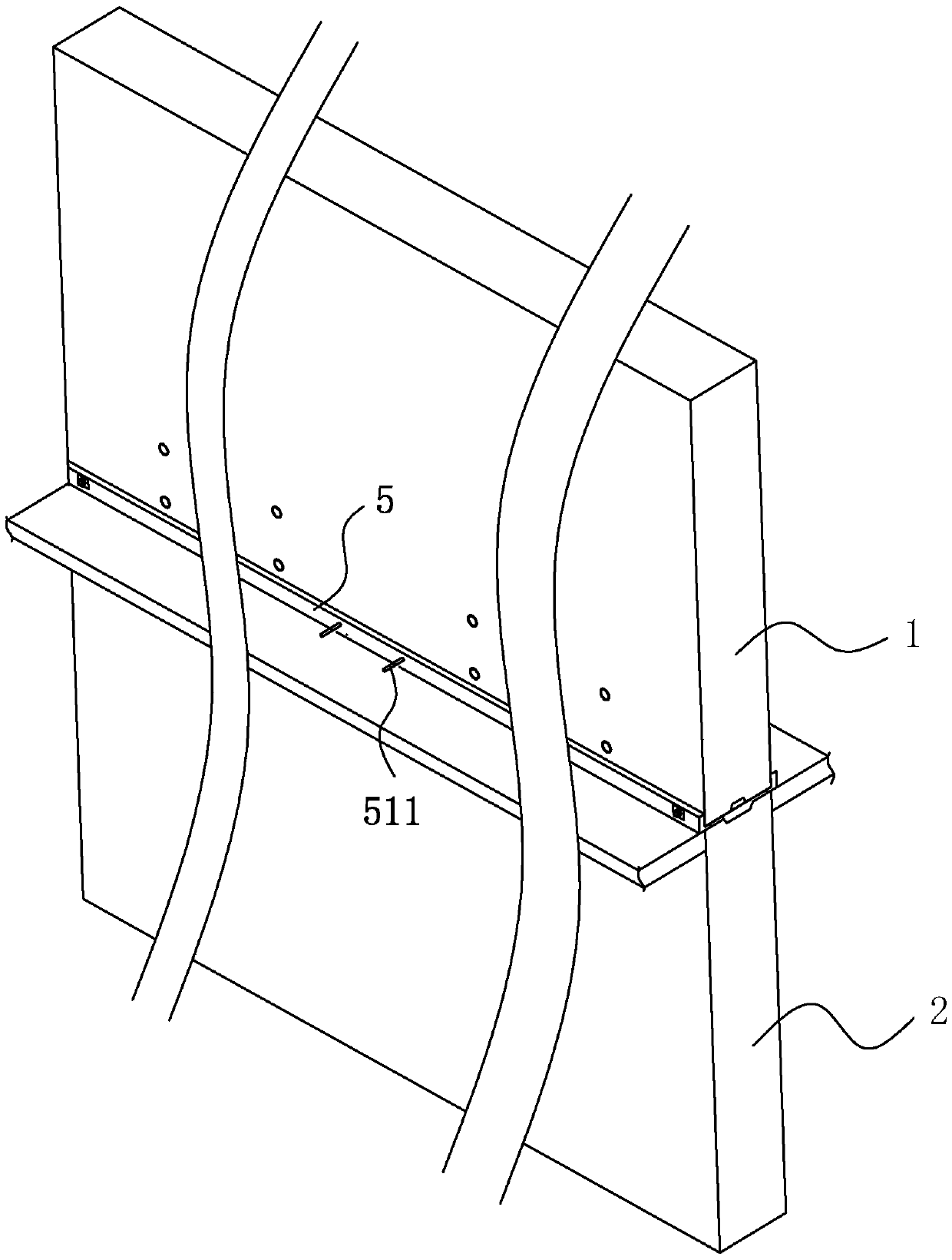
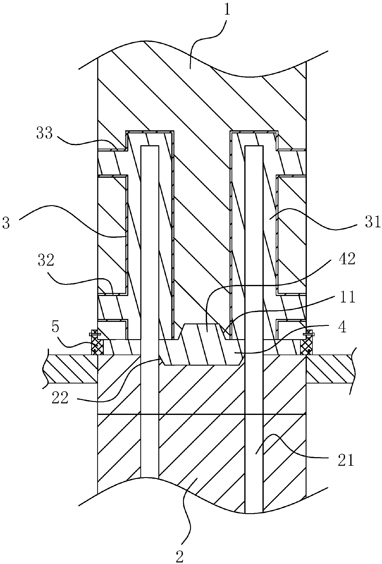
[0042] A shear wall connection structure, refer to figure 2 with image 3 , which includes an upper wall 1 and a lower wall 2, the lower end wall of the upper wall 1 is provided with a number of grouting sleeves 3 on both sides thereof, and the wall of the grouting sleeve 3 is connected with a wall extending to the upper wall 1 External grouting pipe 32 and grouting pipe 33, the grouting pipe 32 is positioned at the lower end of the grouting sleeve 3, and is used for injecting concrete in the grouting sleeve 3; The grouting pipe 33 is positioned at the upper end of the grouting sleeve 3, when draining When concrete is discharged in the grout pipe 33, it means that the inside of the grouting sleeve 3 is full of concrete.

[0043] refer to image 3 , the interior of the lower wall 2 is embedded with several butt reinforcing bars 21, and the upper ends of the butt reinforcing bars 21 extend upwards to the outside of the upper end wall of the lower wall 2; the upper ends of the...


PUM


Abstract

The invention discloses a shear wall connection structure and a construction process thereof, and relates to the technical field of prefabricated shear wall design. A gap exists between the lower endwall of an upper wall body and the upper end wall of a lower wall body. The shear wall connection structure is characterized in that the upper end face of the lower wall body is provided with a slurrypassing groove in the length direction of the upper end face of the lower wall body, and the slurry passing groove communicates with all grouting sleeves; sleeve interior slurry blocks are arranged in the grouting sleeves, and the slurry passing groove is internally provided with a grouting joint filling block which is integrally formed with the sleeve interior slurry blocks; and concrete is injected into the grouting sleeves through a grouting pipe, because of the gravity effect, the concrete downwards flows into the slurry passing groove and forms the grouting joint filling block after being solidified, thus the gap between the upper wall body and the lower wall body is fully filled, and the phenomenon that the gap exists between the upper wall boy and the lower wall body is effectivelyavoided.

Description

technical field [0001] The invention relates to the technical field of prefabricated shear wall design, more specifically, it relates to a shear wall connection structure and construction technology thereof. Background technique [0002] Shear walls, also known as wind-resistant walls or structural walls, are walls in houses or structures that mainly bear horizontal and vertical loads caused by wind loads or earthquakes; currently, shear walls are generally prefabricated in factories, and then passed on-site. docking to complete the installation of the shear wall. [0003] Shear wall connection structure reference in the prior art figure 1 , which includes an upper wall 1 and a lower wall 2, the lower end wall of the upper wall 1 is provided with a number of grouting sleeves 3 on both sides thereof, and the grouting sleeves 3 are in an upright state in the upper wall 1; the grouting sleeves The lower end of the barrel 3 is provided with a grouting pipe 32 extending to the ...

Claims


Application Information

Patent Timeline
Patent Type & Authority Applications(China)
IPC IPC(8): E04B2/56E04B2/00E04C5/16
CPCE04B2/00E04B2/56E04C5/165
Inventor 冯鹏褚国栋
Owner 南通市建筑设计研究院有限公司
Why Eureka
Try Eureka