Automatic ball bullet feeding and shooting mechanism

A firing mechanism and bullet technology, which is applied in the field of ammunition supply and launch, can solve problems such as bullet jamming, easy bullet jamming, and affecting the reliability of ammunition supply, so as to achieve the effect of improving reliability

Active Publication Date: 2019-04-12
ROBOT PHOENIX
View PDF5 Cites 1 Cited by
  • Summary
  • Abstract
  • Description
  • Claims
  • Application Information

AI Technical Summary

Problems solved by technology

[0002] At present, most of the common spherical bullets are fed and fired by means of a dial, that is, the bullet first enters the gap between the two paddles on the dial from the magazine, and then is moved by the dial to the launch nozzle. The position is to rely on the bullet’s own gravity to fall into the launch tube to realize the feeding; in this way, because the spherical bullet in the magazine is basically in a static state, the bullets rub against each other and the support is prone to jamming, and they cannot fall smoothly, resulting in the bullet not being able to be released in time. , into the dial continuously, thereby affecting the reliability of the bullet supply; and the problem of bullet jamming is prone to occur in the bullet delivery process; the above-mentioned problems are more obvious for the occasion of using small soft bullets; the present invention needs to solve the above-mentioned problems Designed a mechanism that is suitable for both hard bullets and soft bullets, and can continuously and reliably carry out bullet delivery, supply, and launch

Method used


Image

  • Automatic ball bullet feeding and shooting mechanism
  • Automatic ball bullet feeding and shooting mechanism

Examples


Embodiment Construction

[0026] The features and principles of the present invention will be described in detail below in conjunction with the accompanying drawings, and the examples given are only used to explain the present invention, not to limit the protection scope of the present invention.

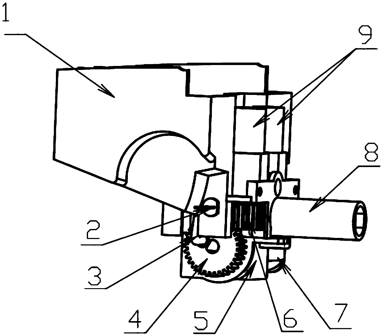
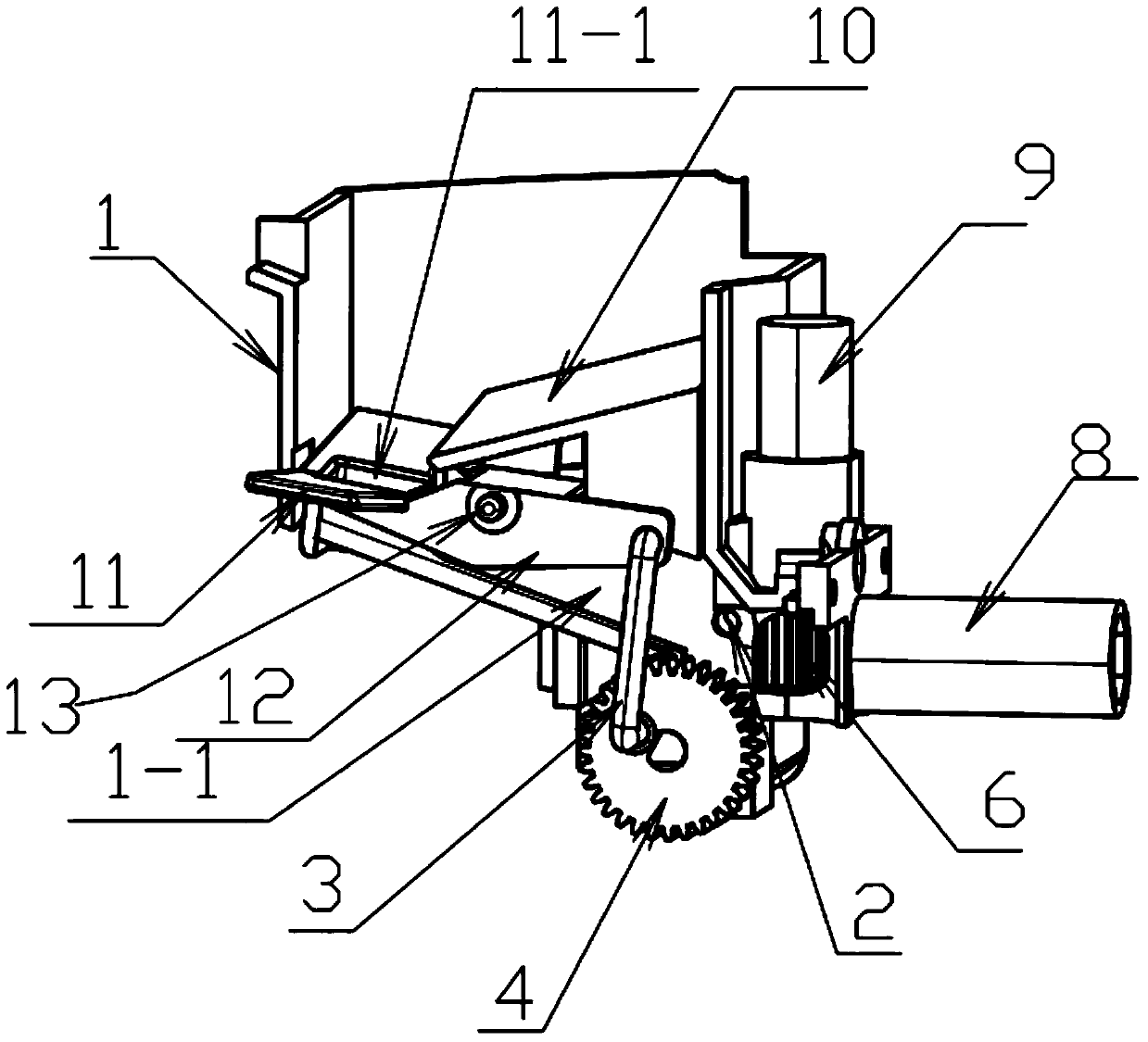
[0027] as attached figure 1 , figure 2 As shown, a sphere automatic feeding and launching device includes a magazine 1, a bomb scrambling plate 11, a magazine bottom plate 10, a bomb feeding motor 7, a bomb feeding wheel 4, and a connecting rod 3, and also includes an infrared detection tube 2 and a launching motor. 9. The launching wheel 6 and the launching tube 8, the upper part of the magazine 1 is a bullet storage space, the lower central part has a bullet conveying channel 1-1, and the second half of the bomb scrambling plate 11 is a "V" shape with slightly higher sides and a lower middle There is a leaking bullet hole 11-1 in the middle, and the front half is a connecting bracket, which is installed ...


PUM


Abstract

The invention relates to an automatic ball bullet feeding and shooting mechanism. The automatic ball bullet feeding and shooting mechanism comprises a bullet bin, a bullet bin bottom plate, a bullet disturbing and bullet feeding part and a shooting part. A bullet disturbing plate is installed inside the bullet bin and is clamped in a groove in the bottom of the bullet bin through a short shaft. Abullet feeding motor is fixed below the bullet bin through a motor gland. A bullet feeding wheel is installed on an output shaft of the bullet feeding motor. The bullet feeding wheel is connected withthe other end of a connecting rod through an eccentric hole in the end surface. An infrared detection tube is divided into an infrared shooting tube and an infrared receiving tube. Two shooting motors are fixed in grooves in the front end of the bullet bin. Two shooting gears are correspondingly installed on output shafts of the two shooting motors. The shooting tube is installed at the foremostpart of the bullet bin and is in butt joint with and communicated with an outlet of a bullet conveying channel of the lower part of the bullet bin. The transportation of a bullet from the bullet bin to the shooting depends entirely on the dead gravity of the bullet, and no additional power is used to force the bullet to move forward, so that the problem of sticking due to extrusion and friction ofthe bullet is avoided, the reliability of the bullet transportation is improved, and the automatic ball bullet feeding and shooting mechanism is suitable for transporting hard bullets or soft bullets.

Description

technical field [0001] The invention relates to the technical field of bomb feeding and launching, in particular to an automatic feeding and launching mechanism for spherical bullets. Background technique [0002] At present, most of the common spherical bullets are fed and fired by means of a dial, that is, the bullet first enters the gap between the two paddles on the dial from the magazine, and then is moved by the dial to the launch nozzle. The position is to rely on the bullet’s own gravity to fall into the launch tube to realize the feeding; in this way, because the spherical bullet in the magazine is basically in a static state, the bullets rub against each other and the support is prone to jamming, and they cannot fall smoothly, resulting in the bullet not being able to be released in time. , into the dial continuously, thereby affecting the reliability of the bullet supply; and the problem of bullet jamming is prone to occur in the bullet delivery process; the above...

Claims


Application Information

Patent Timeline
Patent Type & Authority Applications(China)
IPC IPC(8): F41F1/00
CPCF41F1/00
Inventor 李本月王伟
Owner ROBOT PHOENIX
Why Eureka
Try Eureka