
Secondary equipment state monitoring method based on infrared thermal imaging

A technology of infrared thermal imaging and secondary equipment, which is applied in the field of infrared thermal imaging and can solve the problems of inability to predict accidents and diagnose abnormalities.

Inactive Publication Date: 2019-04-12
GUANGZHOU POWER SUPPLY CO LTD
View PDF5 Cites 3 Cited by
  • Summary
  • Abstract
  • Description
  • Claims
  • Application Information

AI Technical Summary

Problems solved by technology

[0005] The above-mentioned secondary equipment status monitoring method uses the technical means of infrared imaging and the phenomenon that most secondary equipment will have insulation breakdown and even obvious thermal effects before "fault". One monitoring, for the current secondary circuit, including non-device equipment such as contactors, relays, terminal blocks, and outdoor or on-site installations, etc., it provides an effective choice for the few monitoring methods of the current secondary circuit , to solve the defect that some secondary circuits can only be solved after the accident, and cannot be predicted and diagnosed abnormally, so that the operation and maintenance level and initiative of the secondary equipment have been greatly improved. Equipment status evaluation, hidden danger investigation, operation and maintenance inspection, etc. have great significance. It provides an important tool for secondary equipment monitoring, and provides a new basis for judging the operation and maintenance status of the secondary circuit, getting rid of the original The dilemma of insufficient judgment basis

Method used


Image

  • Secondary equipment state monitoring method based on infrared thermal imaging
  • Secondary equipment state monitoring method based on infrared thermal imaging
  • Secondary equipment state monitoring method based on infrared thermal imaging

Examples


Embodiment Construction

[0018] In order to make the above-mentioned purpose, features and advantages of the present application more obvious and understandable, the specific implementation manners of the present application will be described in detail below in conjunction with the accompanying drawings. In the following description, numerous specific details are set forth in order to provide a thorough understanding of the application. However, the present application can be implemented in many other ways different from those described here, and those skilled in the art can make similar improvements without departing from the connotation of the present application, so the present application is not limited by the specific embodiments disclosed below.

[0019] It should be noted that when an element is referred to as being “fixed on” or “disposed on” another element, it may be directly on the other element or there may be an intervening element. When an element is referred to as being "connected to" a...


PUM


Abstract

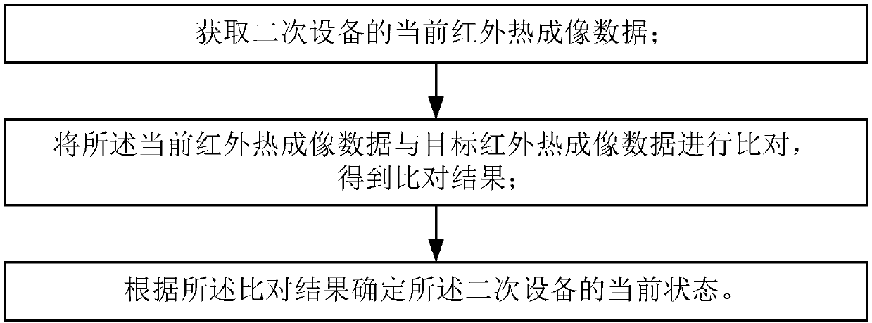
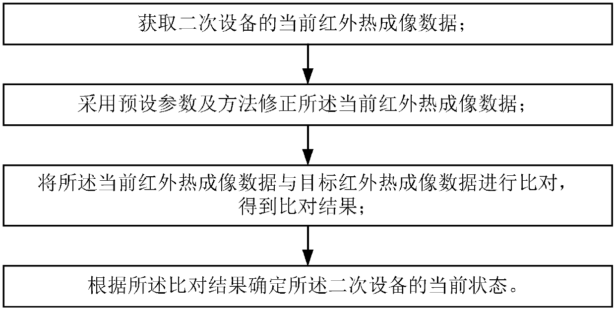
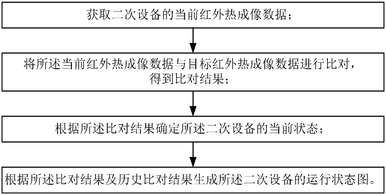
The present application relates to a secondary equipment state monitoring method based on infrared thermal imaging, the method comprises the following steps of: acquiring current infrared thermal imaging data of a secondary equipment; comparing the current infrared thermal imaging data with target infrared thermal imaging data to obtain a comparison result; and determining a current state of the secondary equipment based on the comparison result. According to the infrared imaging technology and the fact that insulation breakdown or obvious thermal effects will happen before most of the secondary equipment ''fail'', an effective choice is provided to the monitoring device of the current secondary circuit, which solves problems that some secondary circuits can only be solved after an accident, and accident prediction and abnormal diagnosis cannot be performed. Therefore, the operation and maintenance level of the secondary equipment and the initiative of operation and maintenance have been greatly improved, and it has a great significance on the status evaluation of secondary equipment, hidden danger investigation, operation and maintenance inspection. Moreover, a new discriminatingbasis for the operation and maintenance state of the secondary circuit is provided, getting rid of the predicament that the original judgment basis is insufficient.

Description

technical field [0001] The present application relates to the technical field of infrared thermal imaging, in particular to a method for monitoring the status of secondary equipment based on infrared thermal imaging. Background technique [0002] Power secondary equipment is to monitor the primary equipment in the power system, including auxiliary equipment for measurement, control, protection, and regulation. It is usually equipment that is not directly related to electrical energy, such as measuring meters, such as voltmeters, ammeters, and power meters. , The electric energy meter is used to measure the electrical parameters in the circuit, etc.; the primary equipment refers to the equipment that directly transmits and distributes electric energy, such as transformers, circuit breakers, isolating switches, power cables, busbars, transmission lines, reactors, lightning arresters, high-voltage fuses , current transformer, voltage transformer, etc. For the equipment and cir...

Claims


Application Information

Patent Timeline
Patent Type & Authority Applications(China)
IPC IPC(8): G01J5/00
CPCG01J5/00G01J2005/0077
Inventor 何涛黄洪康徐强超梁耀彬李一鸣黎志熙刘华沛王键王可何镜如
Owner GUANGZHOU POWER SUPPLY CO LTD
Learn More