Clock signal synchronization

Active Publication Date: 2015-03-03
ANALOG DEVICES INC
View PDF8 Cites 4 Cited by
  • Summary
  • Abstract
  • Description
  • Claims
  • Application Information

AI Technical Summary

Problems solved by technology

If the synchronization signal is unstable during this period—if, for example, it transitions within the setup and hold time—then a component may not generate a reliab

Method used


Image

  • Clock signal synchronization
  • Clock signal synchronization
  • Clock signal synchronization

Examples


Embodiment Construction

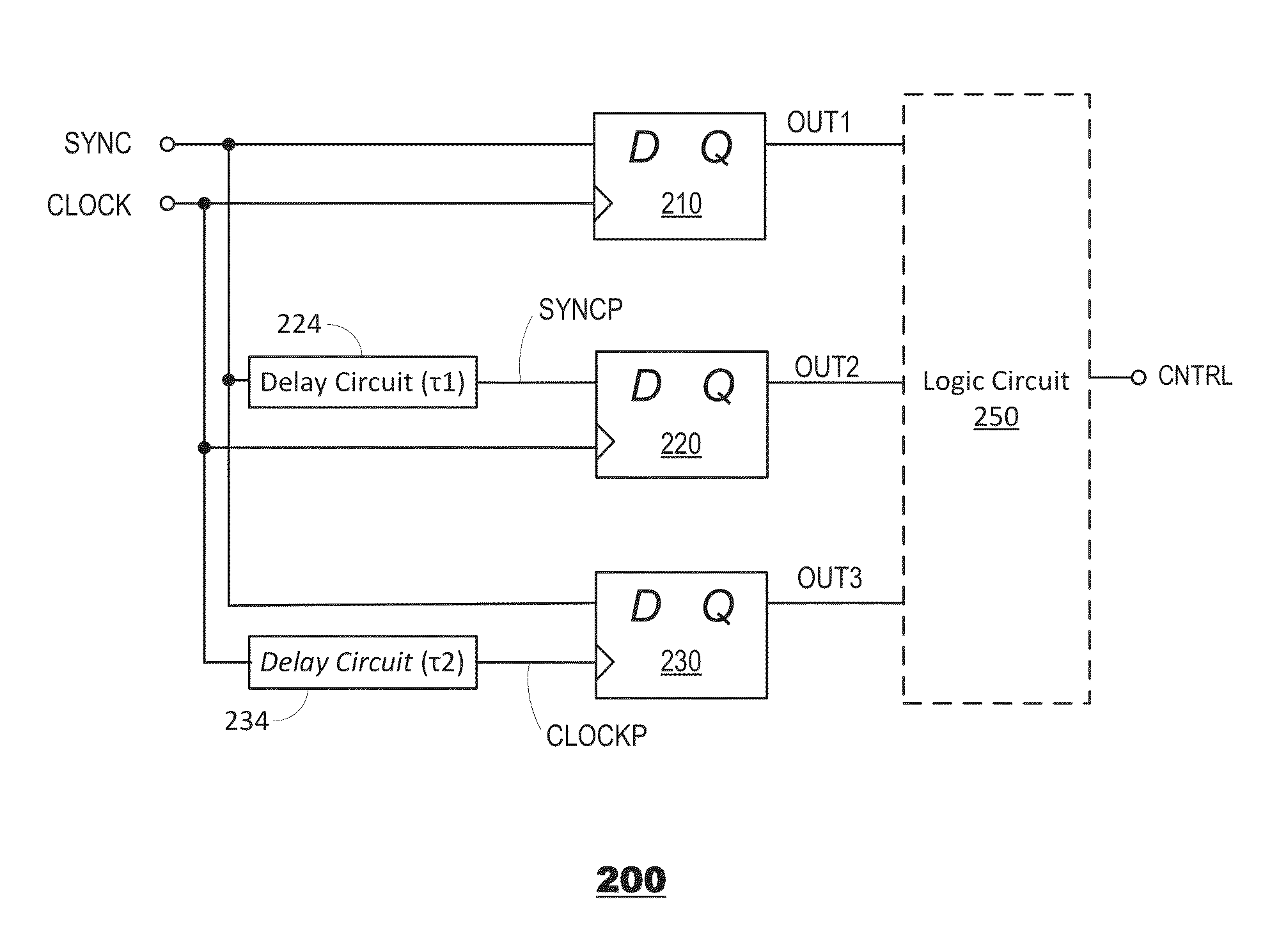
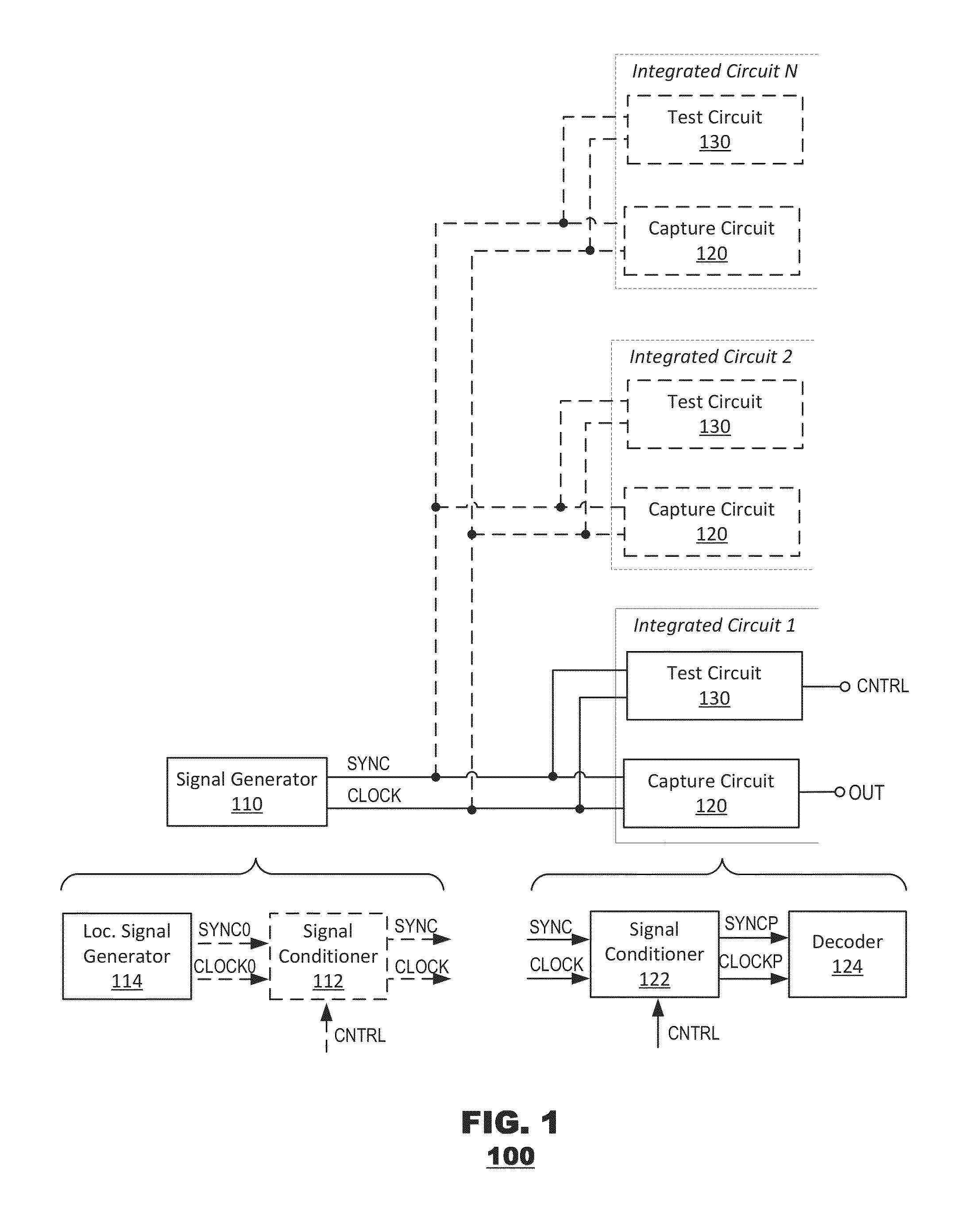
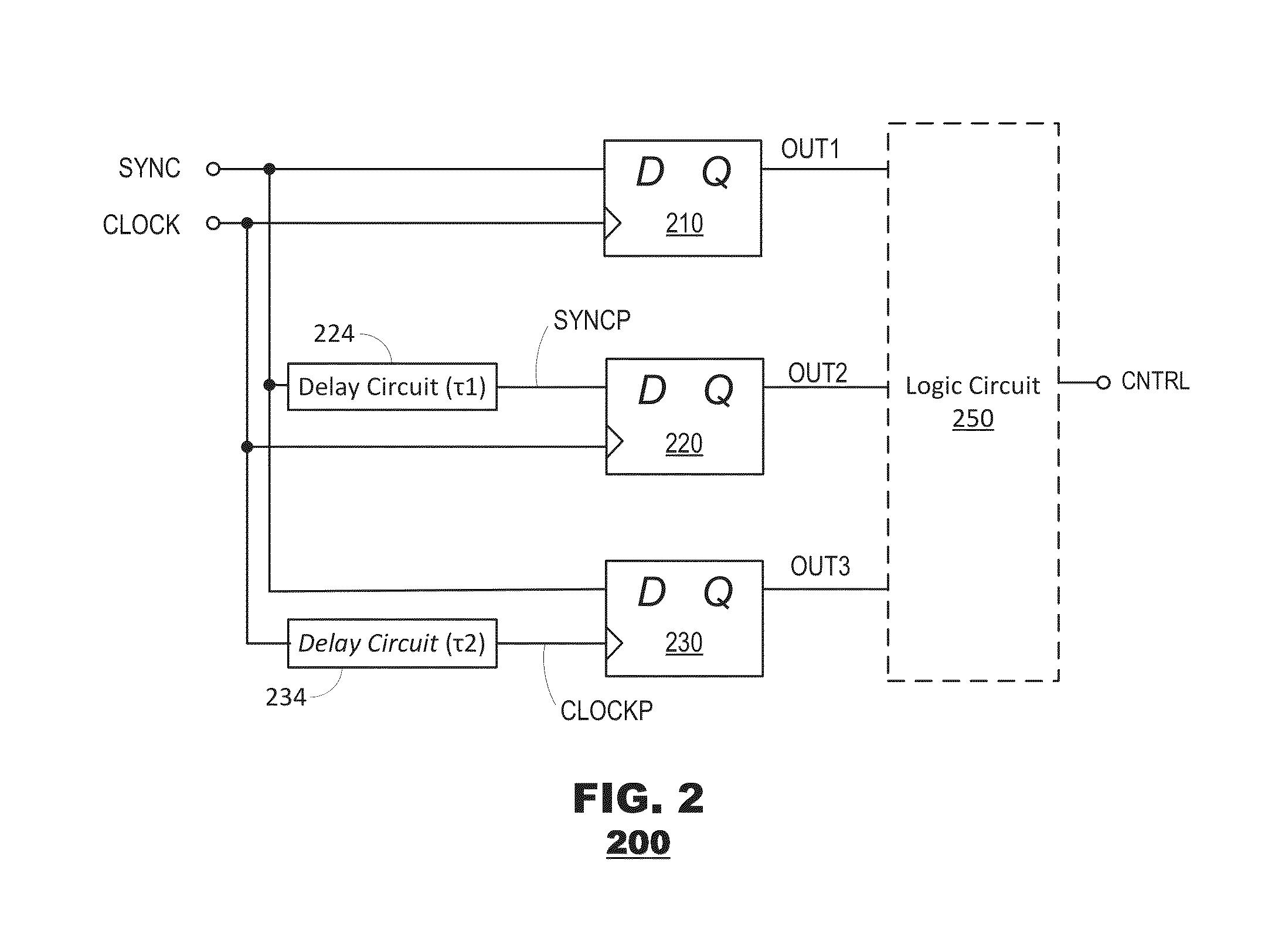
[0011]Embodiments of the present invention provide circuits and methods to regulate timing relationships between a clock signal and a synchronization signal. Specifically, the timing relationship between a capture edge of the clock signal and a transition of the synchronization signal may be controlled to ensure synchronization notwithstanding timing constraints of the circuit. Determining the timing relationship between the capture edge of the clock signal and transition of the synchronization signal may include providing a delayed synchronization signal and a delayed clock signal and comparing how the delayed signals change performance of the circuit. The changes to the output using the delayed synchronization signal may provide what happens before the capture edge of the clock signal. The changes to the output using the delayed clock signal may provide what happens after the capture edge of the clock signal. The disclosed circuits and methods may test and adjust the timing relati...


PUM


Abstract

Circuits and methods are introduced to allow for timing relationship between a clock signal and a synchronization signal to be observed. The observations may include observing the timing relationship between a capture edge of the clock signal and a transition of the synchronization signal. Based on the observations the timing of the synchronization signal transition may be adjusted. Observing the timing relationship may include providing a delayed synchronization signal and a delayed clock signal. The delayed synchronization signal may provide what happens before the capture edge of the clock signal. The delayed clock signal may provide what happens after the capture edge of the clock signal.

Description

FIELD[0001]The subject matter of this application is directed to clock synchronization in circuit systems, and more particularly to synchronization of clock signals provided to multiple chips.BACKGROUND[0002]In electronic systems, there is often a need to control the timing of events. Within a single integrated circuit (e.g., a chip) this may be accomplished by providing an external clock signal or by generating a clock signal internally. When events in multiple circuits need to be coordinated, the same clock signal may be provided to the multiple circuits. Due to variations in the circuits and paths of the clock signals to these circuits, the clock signals at each circuit may drift over time and need to be synchronized. Also internal circuits such as clock multiplier or divider circuits may start up with different initial conditions. In both cases, a synchronization signal may periodically synchronize these clock signals.[0003]In order to successfully synchronize the clock signal t...

Claims


Application Information

Patent Timeline
IPC IPC(8): H03H11/26H03L7/087
CPCH03L7/087H03K3/0375H03K5/135
Inventor MCSHEA, MATTHEW D.BARDSLEY, SCOTT G.DEROUNIAN, PETER
Owner ANALOG DEVICES INC
Why Eureka
Try Eureka