Clamping mechanism of tunnel protective door and wind pressure test device comprising clamping mechanism

A technology of clamping mechanism and protective door, which is applied in the direction of applying stable tension/pressure to test the strength of materials, measuring devices, and testing of machine/structural components, which can solve the constraints of safe application of tunnel protective doors, single test conditions, and testing Small sample size and other issues, to achieve the effect of improving efficiency and convenience, reducing costs, and high loading efficiency

Pending Publication Date: 2019-04-12
CHINA RAILWAY SIYUAN SURVEY & DESIGN GRP
View PDF10 Cites 4 Cited by
  • Summary
  • Abstract
  • Description
  • Claims
  • Application Information

AI Technical Summary

Problems solved by technology

In the structural performance test of the tunnel protective door, the wind pressure test is an important test that the tunnel protective door needs to carry out. The test results can often reflect the application state and life cycle of the tunnel protective door under the action of piston wind. The structure and layout design of the door has excellent guiding significance; at present, the wind pressure test of the protective door of the tunnel can basically only rely on the field test, which not only has certain potential safety hazards, but also the test sample size is small and the test conditions are relatively simple , it is difficult to apply the test results by analogy, and there are large limitations, which restrict the safe application of tunnel protective doors

Method used


Image

  • Clamping mechanism of tunnel protective door and wind pressure test device comprising clamping mechanism
  • Clamping mechanism of tunnel protective door and wind pressure test device comprising clamping mechanism
  • Clamping mechanism of tunnel protective door and wind pressure test device comprising clamping mechanism

Examples


Embodiment Construction

[0042] In order to make the object, technical solution and advantages of the present invention clearer, the present invention will be further described in detail below in conjunction with the accompanying drawings and embodiments. It should be understood that the specific embodiments described here are only used to explain the present invention, not to limit the present invention.

[0043] In addition, the technical features involved in the various embodiments of the present invention described below can be combined with each other as long as they do not constitute a conflict with each other.

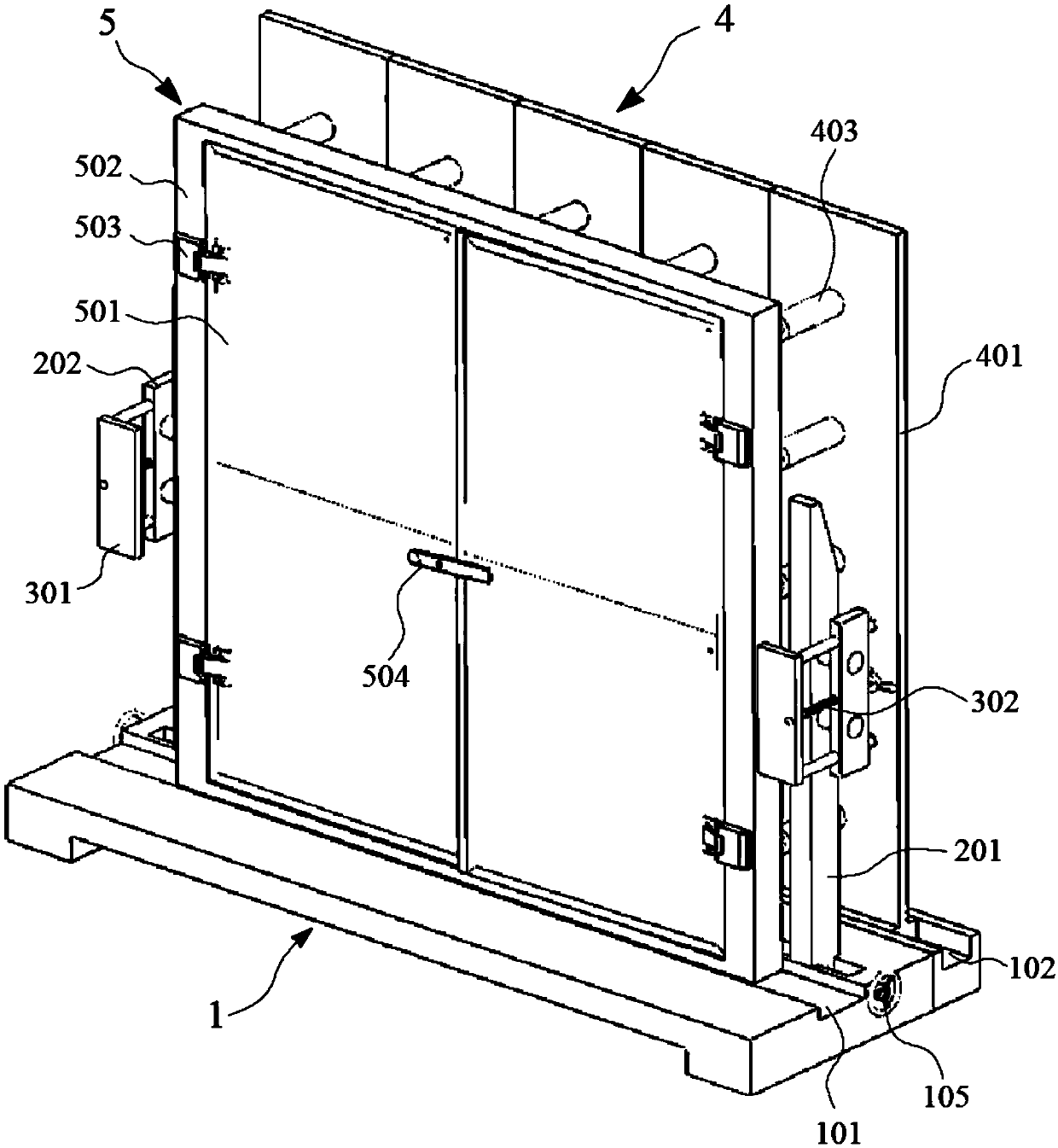
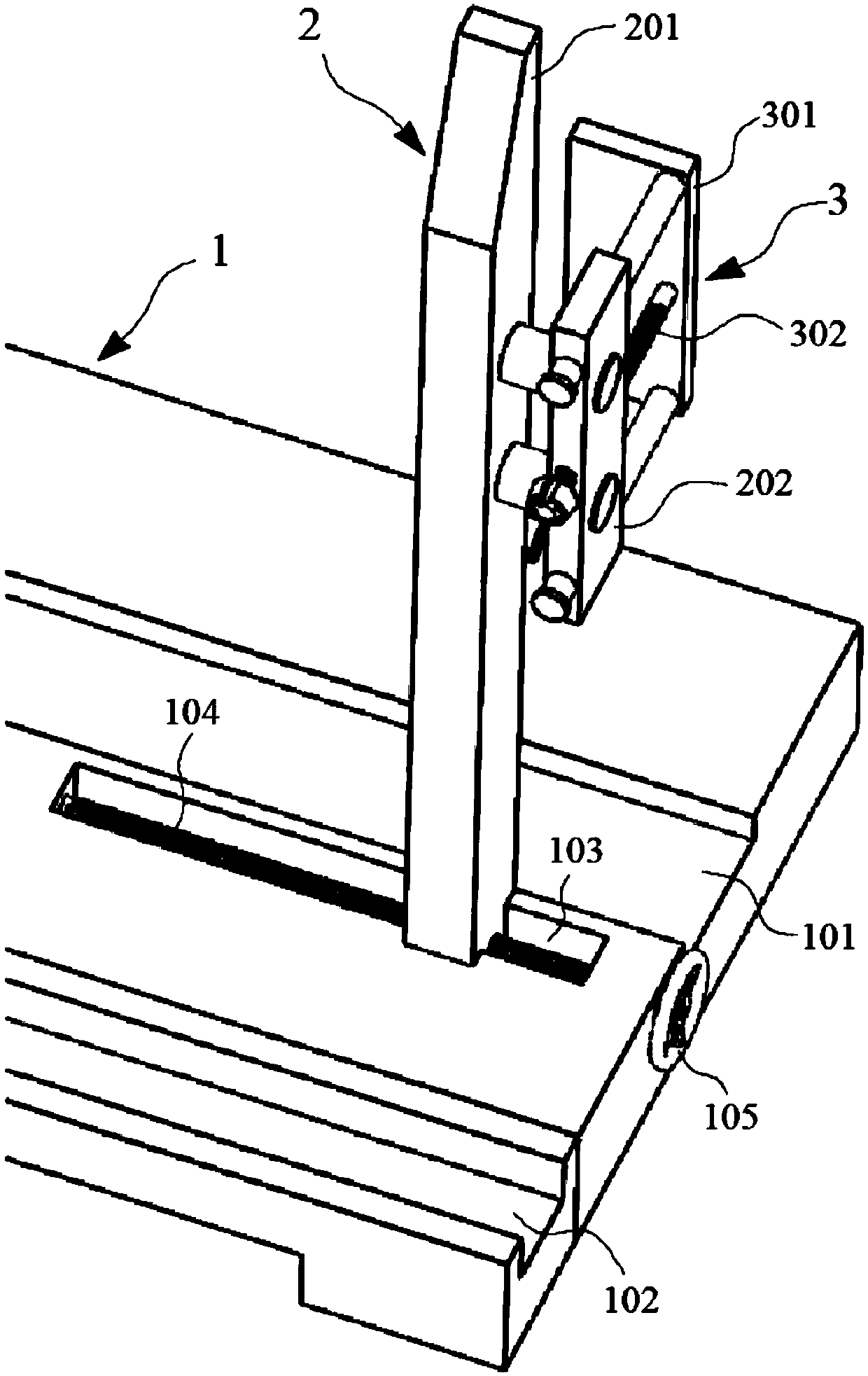
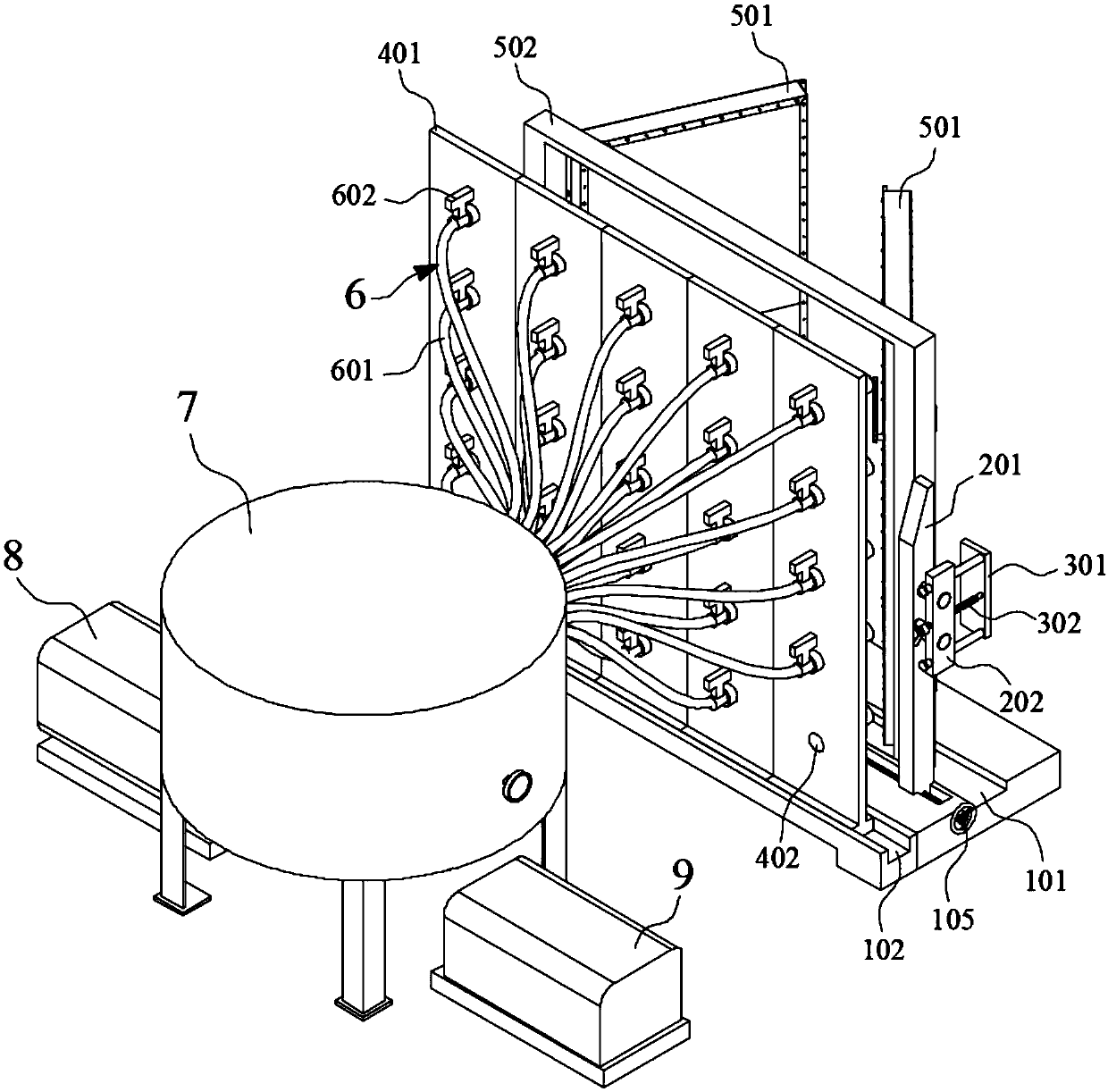
[0044] The clamping mechanism of the tunnel protective door in the preferred embodiment of the present invention is as follows: Figure 1~3 As shown in , where the clamping mechanism includes a base 1, a transverse clamping piece 2 and a longitudinal clamping piece 3; specifically, the base 1 in the preferred embodiment is a plate-shaped structure, which is used to be fixed on the groun...


PUM


Abstract

The invention discloses a clamping mechanism of a tunnel protective door and a wind pressure test device comprising the clamping mechanism, and belongs to the technical field of tunnel protective doordetection. A transverse clamping piece and a longitudinal clamping piece are arranged on a base, so that rapid and stable loading of the tunnel protective door can be realized; and an air path assembly and a wind pressure control assembly are arranged corresponding to the clamping mechanism, so that the state of being subjected to wind pressure of the tunnel protective door in a tunnel can be effectively simulated, and thus a wind pressure test of the tunnel protective door can be accurately realized. The clamping mechanism and the wind pressure test device comprising the clamping mechanism are simple in structure and simple and convenient to control, the state of being subjected to the action of piston wind of the tunnel protective door in the tunnel can be effectively simulated, the selectivity of test schemes is high, the accuracy of test results is high, a basis is provided for structural design and matching installation of the tunnel protective door, the safety and reliability ofapplication of the tunnel protective door are improved, the application cost of the tunnel protective door is reduced, and the application popularization value is excellent.

Description

technical field [0001] The invention belongs to the technical field of tunnel protective door detection, and in particular relates to a clamping mechanism of a tunnel protective door and a wind pressure test device including the clamping mechanism. Background technique [0002] In recent years, the rapid development of my country's railway construction has continuously shortened the "time distance" between various regions. As the speed of railway traffic increases, the requirements for infrastructure construction standards also increase. As an important part of railway infrastructure, railway tunnels play a very important role in the process of railway lines crossing natural elevation obstacles or plane obstacles. [0003] According to the different application environments and requirements of railway tunnels, their setting forms are also different, such as single-hole single-track tunnel, double-hole single-track tunnel, single-hole double-track tunnel, etc. In a railway t...

Claims


Application Information

Patent Timeline
Patent Type & Authority Applications(China)
IPC IPC(8): G01M99/00G01N3/04G01N3/12G01B21/32
CPCG01B21/32G01M99/007G01N3/04G01N3/12
Inventor 何翔耿明张浩殷勤史明红张俊岭邱绍峰周明翔刘辉孙骥
Owner CHINA RAILWAY SIYUAN SURVEY & DESIGN GRP
Why Eureka
Try Eureka