A kind of optical lens detection equipment and detection method

A technology of optical lenses and testing equipment, applied in the testing of optical instruments, measuring devices, and testing of machine/structural components, etc., can solve the problems of inconvenient testing, affecting the laser testing accuracy, trouble, etc., and achieve convenient testing, stable fixing effect, good size effect

Active Publication Date: 2021-08-31
南京宝凯通机械设备有限公司
View PDF14 Cites 0 Cited by
  • Summary
  • Abstract
  • Description
  • Claims
  • Application Information

AI Technical Summary

Problems solved by technology

[0005] The above-mentioned existing technical solutions have the following defects: the outer surface of the optical lens must be attached with black ink to be detected, and the attachment process includes soaking and drying, and the black ink needs to be washed off after the detection, which is very troublesome
When placing the optical lens in the bracket and adjusting the position of the optical lens through the pressing mechanism, you need to be very careful to avoid scratching the black ink on the optical lens. Once it is scratched, it will affect the detection accuracy of the laser and make the detection inconvenient.

Method used


Image

  • A kind of optical lens detection equipment and detection method
  • A kind of optical lens detection equipment and detection method
  • A kind of optical lens detection equipment and detection method

Examples


Embodiment 1

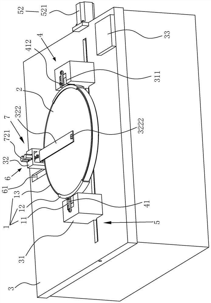
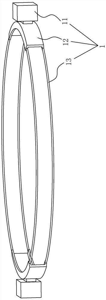
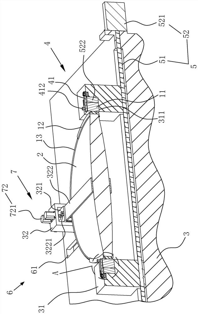
[0046] refer to figure 1 and 2 , is an optical lens inspection device disclosed in the present invention, which includes a horizontally arranged inspection frame 3 and a reference base 1 fixed to the lens 2 . The reference seat 1 includes positioning seats 11 symmetrically arranged on both sides of the lens 2 , and fitting strips 12 made of flexible rubber are fixed on opposite sides of the two positioning seats 11 . The length of the fitting strip 12 is greater than the length of the positioning seat 11, and the cross-sectional shape of the fitting strip 12 is a V shape opposite to the bending direction. When the fitting strip 12 abuts against the lens 2, the fitting strip 12 is in a deformed state. Elastic cords 13 are arranged between the fitting strips 12 for connecting the opposite ends of the two fitting strips 12 , the number of the elastic cords 13 is four and a group of two is used. Two sets of elastic cords 13 are respectively arranged beside the two ends of the fi...

Embodiment 2

[0058] A method for detecting an optical lens disclosed by the present invention comprises the following steps:

[0059] Step 1: Manually fit the lens and the fitting strip so that the two positioning seats are symmetrically fixed on both ends of the lens in the radial direction;

[0060] Step 2: Fit the positioning seat into the positioning groove, drive the support frames to slide close to each other through the sliding mechanism to clamp the positioning seat and the lens horizontally, and fix the positioning seat vertically in the positioning groove through the fixing parts;

[0061] Step 3: Drive the offset frame to slide horizontally through the offset mechanism until the vertical projection of the metal sheet on the lens coincides with the center of the lens;

[0062] Step 4: Drive the two metal sheets vertically close to each other and slide to fit the lens through the bonding mechanism, and judge whether the metal sheet is at the lowest level with the lens by whether t...


PUM


Abstract

The invention relates to an optical lens inspection device and a detection method. The inspection device includes a detection frame and a reference seat fixed to the lens. The reference seat includes positioning seats symmetrically arranged on both sides of the lens. The rope is fixed on the lens, and there are two support frames slidingly connected to the detection frame along the length direction of the detection frame. There is an offset frame slidingly connected in the width direction, and two lifting blocks are connected to the offset frame sliding along the vertical direction. The side of the lifting block close to the support frame is horizontally fixed with a metal sheet, and the end faces of the two metal sheets are separated. An infrared first displacement sensor and an offset block are fixed, and a display and a second distance measuring sensor for detecting the distance between the two lifting blocks are also included. The invention has the technical effect of conveniently detecting the thickness of the lens without damaging the lens.

Description

technical field [0001] The invention relates to the technical field of optical lens detection, in particular to an optical lens detection device and detection method. Background technique [0002] The collimator is mainly an optical instrument used to generate parallel light beams. It is an important tool for installing and adjusting optical instruments, and it is also an important part of optical measuring instruments. The collimator is composed of a light source, reticle or star point plate, focusing mechanism, objective lens, mechanical housing, etc. The objective lens is a kind of optical lens, and its quality directly affects the use effect of the collimator. In the field of optics, the three basic parameters of the lens are the center thickness, the refractive index and the radius of curvature, and the processing error of the center thickness of the lens is an important factor affecting the imaging of the optical system. Therefore, detecting the thickness of optical l...

Claims


Application Information

Patent Timeline
Patent Type & Authority Patents(China)
IPC IPC(8): G01M11/00
CPCG01M11/00
Inventor 符传岭汪德峰薛松
Owner 南京宝凯通机械设备有限公司
Why Eureka
Try Eureka