Rapid pre-pressing device for contact spring

A contact spring, fast technology, applied in the direction of electrical components, electric switches, circuits, etc., can solve the problem of high energy in the design position of the compression spring, and achieve the effect of strong economy and simple and reliable structural adjustment

Inactive Publication Date: 2019-04-12
SHANGHAI PINGGAO TIANLING SWITCHGEAR CO LTD +2
View PDF3 Cites 2 Cited by
  • Summary
  • Abstract
  • Description
  • Claims
  • Application Information

AI Technical Summary

Problems solved by technology

[0003] The technical problem to be solved by the present invention aims at the problem that the compression spring needs to be compressed to the design position, and then the positioning process is performed by a cylindrical pi

Method used


Image

  • Rapid pre-pressing device for contact spring
  • Rapid pre-pressing device for contact spring
  • Rapid pre-pressing device for contact spring

Examples


Embodiment Construction

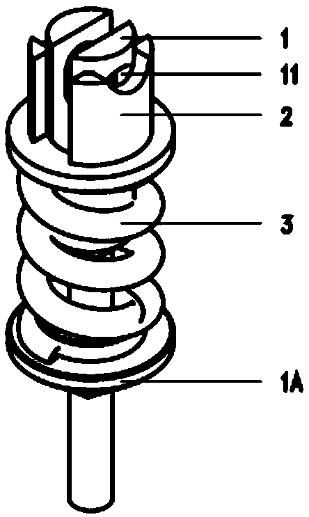
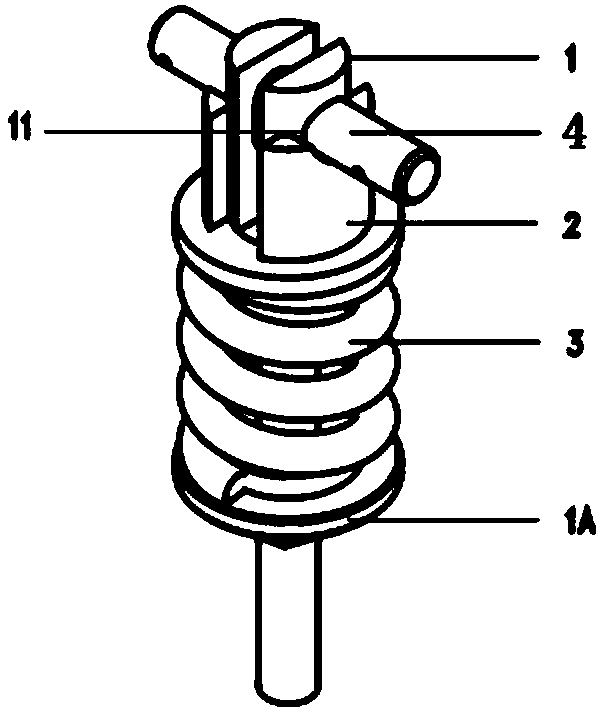
[0015] In order to make the present invention's technical means, creative features, goals and effects easy to understand, below in conjunction with specific illustrations ( figure 1 , figure 2 , image 3 ), for further elaboration.

[0016] see figure 1 and figure 2 , the contact spring assembly shown in the figure includes a guide rod 1, an upper contact spring seat 2, a compression spring 3 and a lower contact spring seat 1A, the lower contact spring seat 1A is fixed on the guide rod 1, and the upper contact spring The seat 2 and the compression spring 3 are sleeved on the guide rod 1, and the compression spring 3 is located between the upper contact spring seat 2 and the lower contact spring seat 1A. After preloading, the cylindrical pin hole 11 of the guide rod 1 exposes the upper contact spring seat 2, and a cylindrical pin 4 passes through the cylindrical pin hole 11 to force the upper contact spring seat 2 to move in the direction of the downward contact spring se...


PUM


Abstract

The invention discloses a rapid pre-pressing device for a contact spring. The rapid pre-pressing device comprises a base, a contact seat support and a cam support, a cam and a guiding strip, wherein the contact seat support and the cam support are arranged on the base at intervals along the axis direction of the base; a clamping hole used for clamping an upper contact spring seat in a contact spring assembly is formed in the contact seat support; the cam is arranged on the cam support in an eccentric axially mode; an operation handle is arranged on the cam; the guiding strip is glidingly arranged on the base; a pin shaft is fixed on the guiding strip, and the first end of the pin shaft is in contact with the cam peripheral surface of the cam; and a guide rod hole is formed in the second end of the pin shaft. The rapid pre-pressing device can be applied to a rapid pre-pressing device of a compression spring, and the assembling mode which cannot be realized by general hand force can be effectively realized; the lever and the cam principle are adopted, so that different stroke changes can be realized by adjusting different cams, and therefore the compression spring compression designof any position can be realized. According to the rapid pre-pressing device, the structure adjustment is simple and reliable, and the implementation scheme is high in economical efficiency.

Description

technical field [0001] The invention relates to the technical field of switchgear, in particular to a quick preloading device for a contact spring. Background technique [0002] The contact spring assembly is an important component to ensure the characteristics of the vacuum interrupter of the circuit breaker cabinet, and directly affects the breaking and closing capabilities of the vacuum interrupter. How to ensure the assembly of the contact spring is an important issue that we need to solve, especially to ensure efficient installation, consistent process and safety in the installation process. Combining vacuum arc extinguishing technology and contact material characteristics can effectively improve short-circuit breaking and high-efficiency arc control capabilities, and meet the performance of closing short-circuit current and breaking fault current. Contents of the invention [0003] The technical problem to be solved by the present invention aims at the problem that ...

Claims


Application Information

Patent Timeline
IPC IPC(8): H01H11/04
Inventor 张佳飞邬建刚顾晓冬
Owner SHANGHAI PINGGAO TIANLING SWITCHGEAR CO LTD
Why Eureka
Try Eureka